Using the Composite Shape nodes
Use the Composite Shape nodes to combine shape nodes using Boolean operations on the geometry of the nodes. The Composite Shape node renders this composite geometry.
You can use a Composite Shape node to combine shapes in the Line, Ellipse, Path, Rectangle, and Composite Shape nodes.
Grouping shapes
To group shapes:
Create the 2D or 3D shape nodes that you want to group.
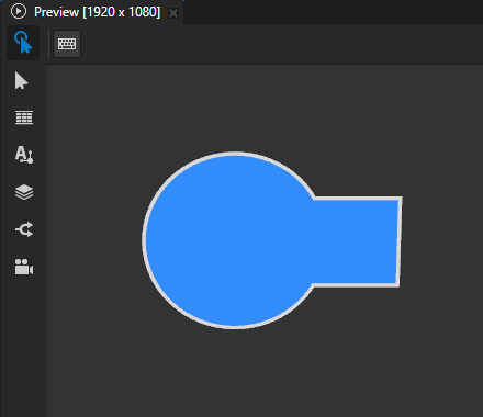
For example, in the Node Tree, create an Ellipse 3D node and a Rectangle 3D node. Position the nodes so that they overlap partially.
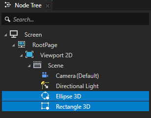
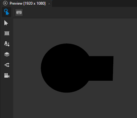
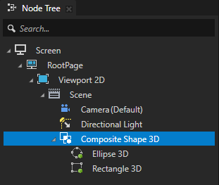
Create a Composite Shape node. Drag the shape nodes, which you want to group, to the Composite Shape node.
For example, in the Node Tree, create a Composite Shape 3D node, and drag the Ellipse 3D and Rectangle 3D nodes to the Composite Shape 3D node.
Note
The Composite Shape 3D node flattens the geometry of its child shape nodes along the z axis. For example, this happens when you rotate a child node of a Composite Shape 3D node along the x or y axis. The result looks as if you used an orthographic camera to view the shapes along the z axis of the Composite Shape 3D node.
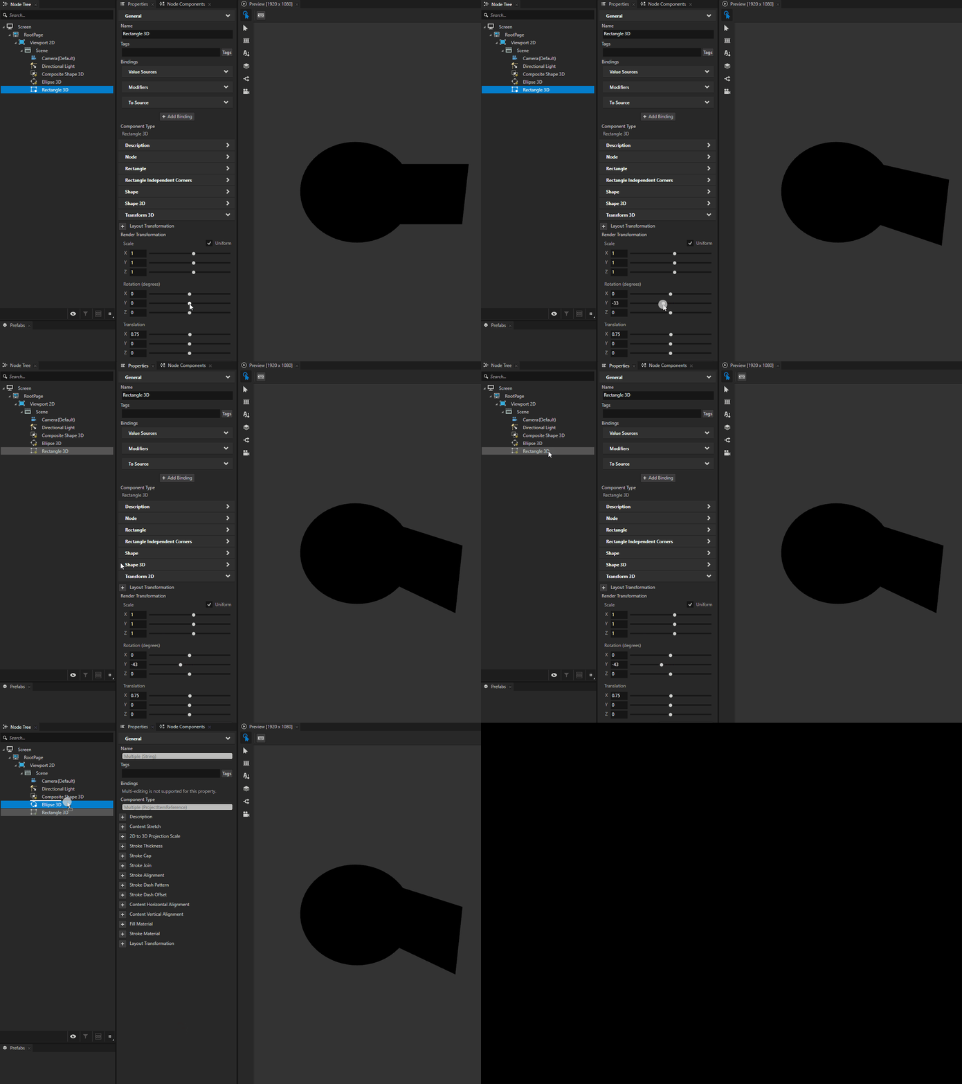
Select the Composite Shape node and in the Properties:
Add and set the properties that set the appearance of the shapes that you group. See Filling a shape and Using stroke.
Kanzi applies the values of these properties to the combined shape of the nodes in the Composite Shape node.
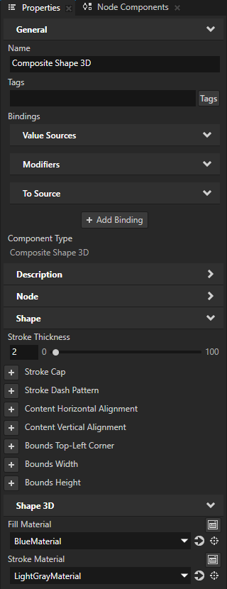
For example, in the Composite Shape 3D node set the Fill Material, Stroke Material, and Stroke Thickness properties.
If any of the nodes that you group use non-default alignment, add and set the Layout Width and Layout Height properties.
Select one of the descendants of the Composite Shape node. In the Properties, add the Composite Shape > Boolean Operation property and set it to the operation that you want to apply to these geometries:
The underlying geometry formed by those descendants of the Composite Shape node that are in the node tree above the node in which you set the Boolean Operation property.
The shape of the node in which you set the Boolean Operation property.
These are the available boolean operations:
Union renders the combined shape that contains the area of all descendants of the Composite Shape node. This is the default operation.
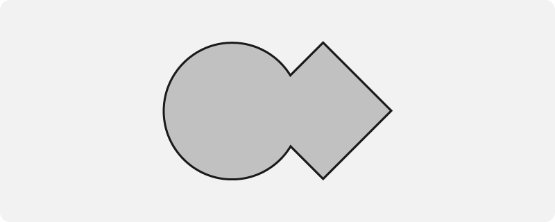
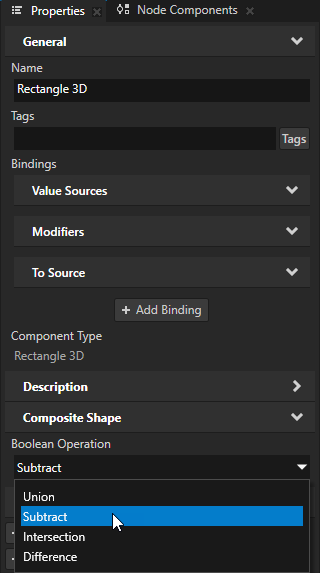
Subtract deducts the shape of the node from the underlying geometry.
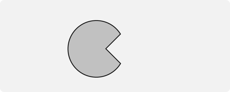
Intersection renders the area where the shape of the node overlaps the underlying geometry.

Difference renders the area where the shape of the node does not overlap the underlying geometry.
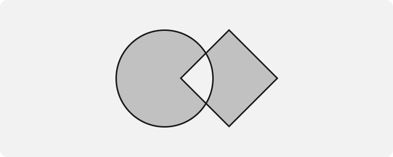
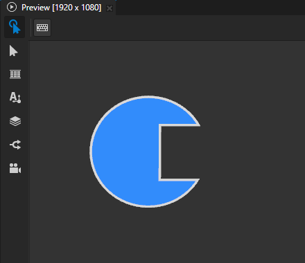
For example, in the Node Tree, select the Rectangle 3D node, which is below the Ellipse 3D node. In the Properties, add the Composite Shape > Boolean Operation property and set it to Subtract.
This way you deduct the shape of the Rectangle 3D node from the shape of the Ellipse 3D node.
Using stroke geometry to group shapes
When you use a Composite Shape node to group shapes, Kanzi by default uses fill as the source for the composited shape.
You can use the Composite Shape > Source property to set Kanzi to use either stroke or both fill and stroke as the source.
To use stroke geometry to group shapes:
Use a Composite Shape to group shapes. See Grouping shapes.


Select one of the descendants of the Composite Shape node. In the Properties, add and set:
Composite Shape > Source to:
Stroke to use the stroke of the node as the source
Fill and stroke to use both fill and stroke as the source
This sets Kanzi to combine the fill and stroke of the shape and use the resulting geometry as the source.
Stroke Thickness to the width of the stroke that you want use
For example, set Source to Stroke and Stroke Thickness to 12.
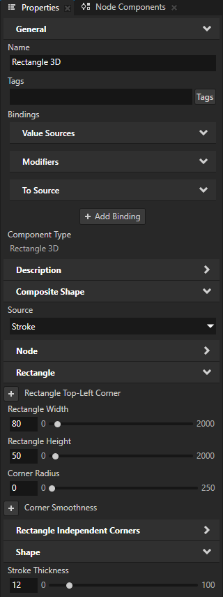
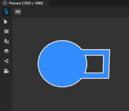
In the Properties, add the Composite Shape > Boolean Operation property and set it to the operation that you want to apply to these geometries:
The underlying geometry formed by those descendants of the Composite Shape node that are in the node tree above the node in which you set the Boolean Operation property.
The stroke of the node in which you set the Boolean Operation property.
These are the available boolean operations:
Union renders the combined shape that contains the underlying geometry and the stroke of the node.
This is the default operation.
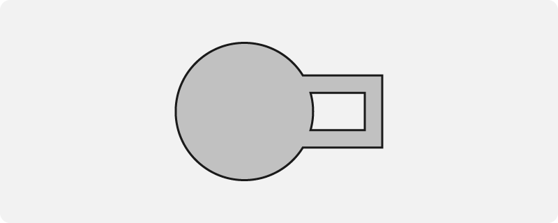
Subtract deducts the stroke of the node from the underlying geometry.
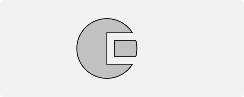
Intersection renders the area where the stroke of the node overlaps the underlying geometry.

Difference renders the area where the stroke of the node does not overlap the underlying geometry.
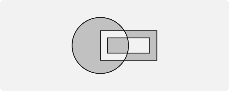
For example, set Boolean Operation to Subtract.
This way you deduct the stroke of the node from the underlying geometry.

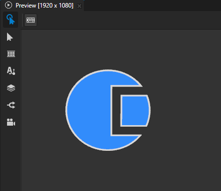
Setting the input area for a Composite Shape 2D node
When you enable hit testing for a node with the Input > Hit Testable property, the entire area of that node receives input by default.
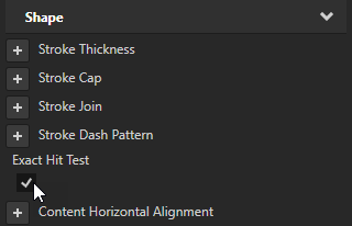
To make only the area formed by the composited geometry of the shapes in a 2D shape node receive input, in the Node Tree or Prefabs, select that node and in the Properties, add and enable the Shape > Exact Hit Test property.

To learn about handling user input in Kanzi, in the Kanzi framework documentation, see Working with > Input.