Using the Line nodes
Use the Line nodes to draw straight lines.
Creating a line
To create a line:
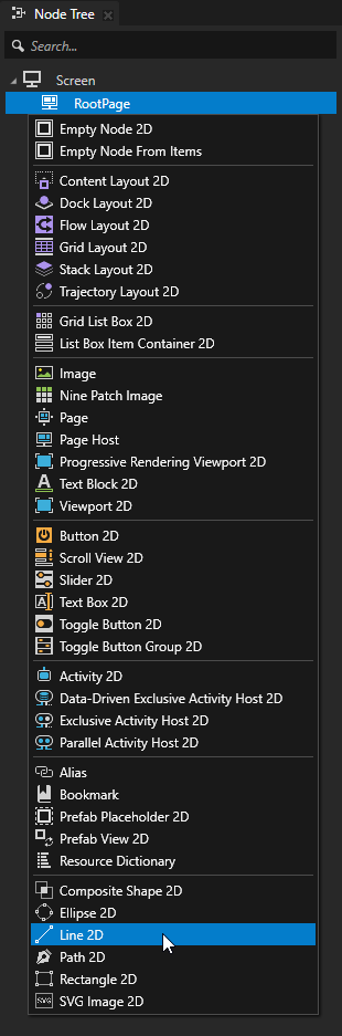
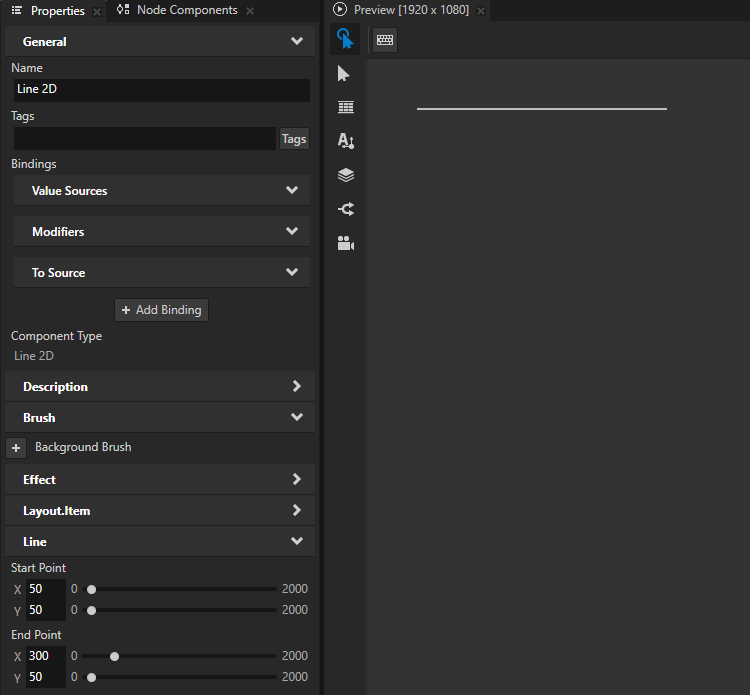
In the Node Tree or Prefabs, press Alt and right-click the node where you want to create a Line node and select either Line 3D, or Line 2D.
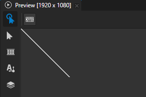
Kanzi Studio draws a white line that starts from the top-left corner and ends in the bottom-right corner of the Line node.
You can create a 3D node only in a 3D node, such as the Scene node, and a 2D node only in a 2D node.
To set the length and orientation of the line, in the Properties, set:
Start Point to the position along the x and y axis where you want the line to start
End Point to the position along the x and y axis where you want the line to end
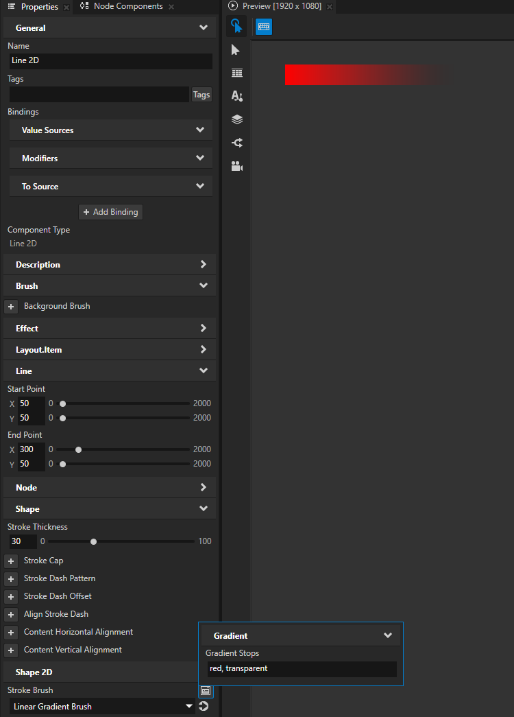
To define the appearance of the line, set the style of its stroke. See Using stroke.
Setting the input area for a Line 2D node
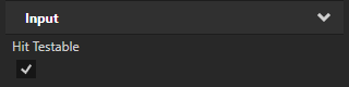
When you enable hit testing for a node with the Input > Hit Testable property, the entire area of that node receives input by default.
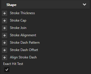
To make only the area formed by the composited geometry of the shapes in a 2D shape node receive input, in the Node Tree or Prefabs, select that node and in the Properties, add and enable the Shape > Exact Hit Test property.
To learn about handling user input in Kanzi, in the Kanzi framework documentation, see Working with > Input.
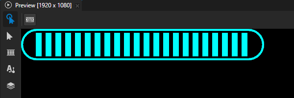
Creating a loading bar
You can use a Line node to create a loading bar.
To create a loading bar:
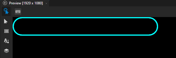
In the Node Tree or Prefabs, create a node that you use to draw a frame for the loading bar.
For example:
In the Prefabs, create a Rectangle 2D prefab and name it Loading Bar.
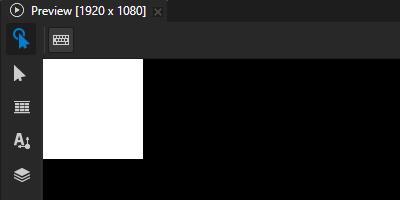
In the Prefabs, double-click the prefab that you created to open only that prefab in a Preview window tab.
This way, you can edit the prefab and see the result of your edits without instantiating the prefab.
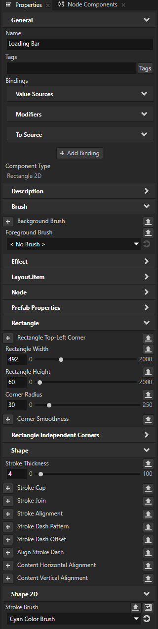
In the Properties, add and set:
Rectangle Width and Rectangle Height to set the size of the loading bar frame
For example, set Rectangle Width to 492 and Rectangle Height to 60.
Corner Radius to the amount of roundness that you want for the corners of the loading bar frame
For example, set it to 30.
Foreground Brush to < No Brush >
Stroke Brush to the color brush that you want to use to paint the frame
Stroke Thickness to set the width of the frame
For example, set it to 4.
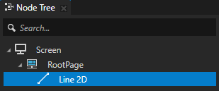
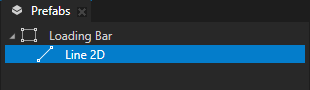
In the node that you created in the previous step, create a Line node.
For example, in the Rectangle 2D prefab, create a Line 2D node.
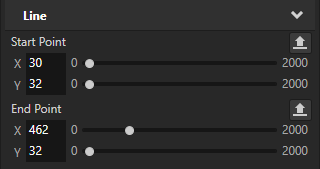
In the Properties, set the Start Point and End Point properties to make the line span across the loading bar frame.
For example, set:
Start Point X to 30
Start Point Y to 32
End Point X to 462
End Point Y to 32
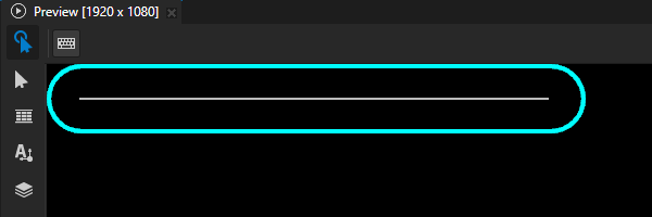
Define the appearance of the loading bar.
For example, in the Properties, add and set:
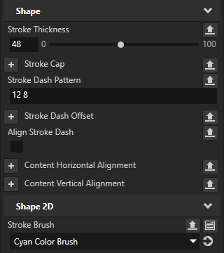
Stroke Thickness to 48
This way you set the height of the bar.
Stroke Brush to the color brush that you want to use to paint the loading bar
(Optional) To use dashed stroke:
Stroke Dash Pattern to set the length of the alternating dashes and gaps in the stroke
Align Stroke Dash to disabled
The Align Stroke Dash property indicates whether Kanzi Shapes scales the dash pattern to fit such that it repeats at least once and always in multiples of the complete pattern. When this property is enabled and you adjust the length of the line, the lengths of the dashes and gaps change.
When you disable this property, the lengths of the dashes and gaps stay the same when you adjust the length of the line.
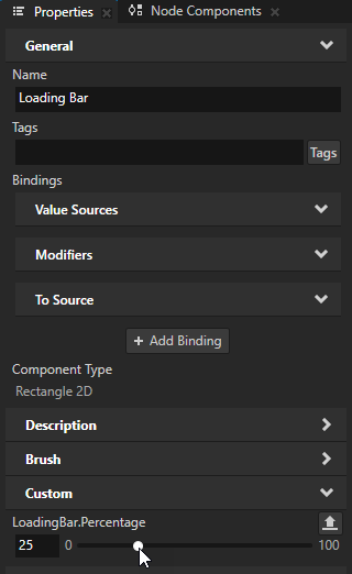
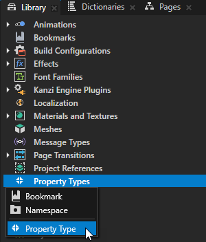
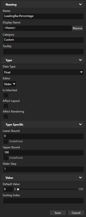
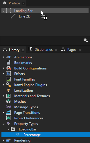
In the Library > Property Types, create a Property Type and set:
Name to LoadingBar.Percentage
Upper Bound to 100
Slider Step to 1
From the Library > Property Types, drag the LoadingBar.Percentage property type to the Prefabs and drop it on the Loading Bar prefab.
Control the length of the loading bar with the LoadingBar.Percentage property.
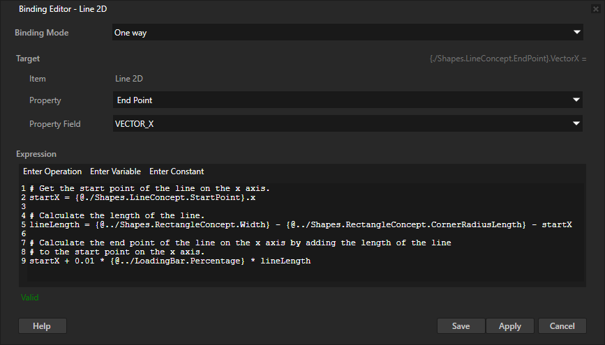
For example, in the Prefabs, select the Line 2D node. In the Properties, click + Add Binding and in the Binding Editor, set:
Property to End Point
Property Field to VECTOR_X
Expression to
# Get the start point of the line on the x axis.
startX = {@./Shapes.LineConcept.StartPoint}.x

# Calculate the length of the line.
lineLength = {@../Shapes.RectangleConcept.Width} - {@../Shapes.RectangleConcept.CornerRadiusLength} - startX

# Calculate the end point of the line on the x axis by adding the length of the line
# to the start point on the x axis.
startX + 0.01 * {@../LoadingBar.Percentage} * lineLength
Click Save.
To control the loading bar, in the Prefabs, select the Loading Bar prefab and in the Properties, adjust the value of the LoadingBar.Percentage property.