Using stroke
Use stroke to define the appearance of a line or outline of a shape.
Setting the stroke of a 2D shape
To set the style of the stroke of a 2D shape:
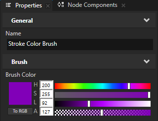
In the Library > Materials and Textures > Brushes, create the brush that you want to use to define the appearance of a line or outline of a shape.
For example, create a Color Brush.
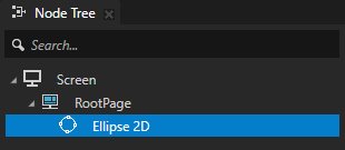
Create or select a shape node whose stroke you want to set.
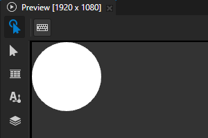
For example, in the Node Tree, create an Ellipse 2D node.
When you create a closed 2D shape, that shape by default has a white fill and no stroke.
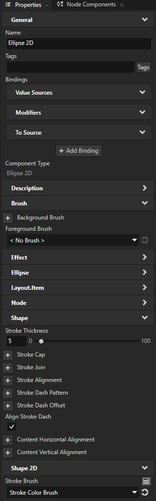
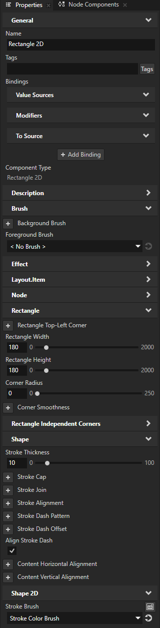
In the Properties, add and set:
Stroke Brush to the brush that you created
Stroke Thickness to the width that you want for the outline of the shape
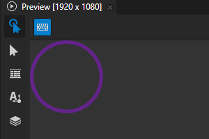
(Optional) Foreground Brush to the brush that you want to use to fill the shape
To draw the shape using only the stroke and no fill, set Foreground Brush to < No Brush >.
Setting the stroke of a 3D shape
To set the style of the stroke of a 3D shape:
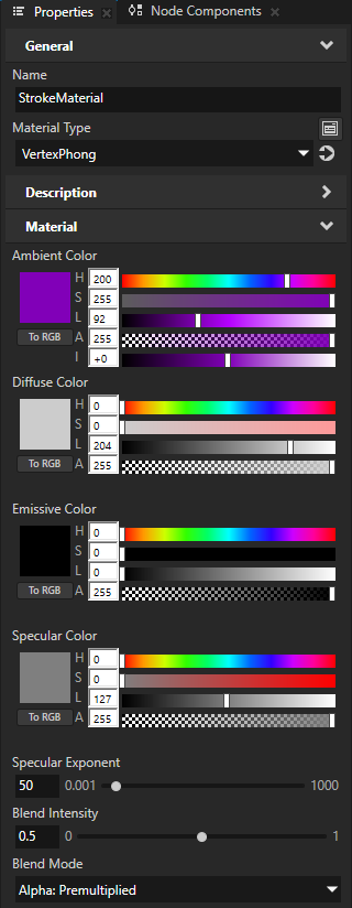
In the Library > Materials and Textures, create the material that you want to use to define the appearance of a line or outline of a shape.
For example, create a material that uses the VertexPhong material type.
Tip
If your project does not contain the VertexPhong material type, in the Library > Materials and Textures, press Alt and right-click Material Types, and select VertexPhong.
Create or select a 3D shape node whose stroke you want to set.
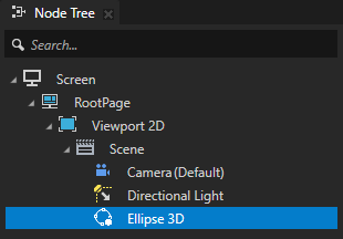
For example, in the Node Tree, create an Ellipse 3D node.
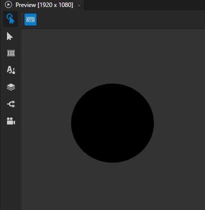
When you create a closed 3D shape, that shape by default has a black fill and no stroke.
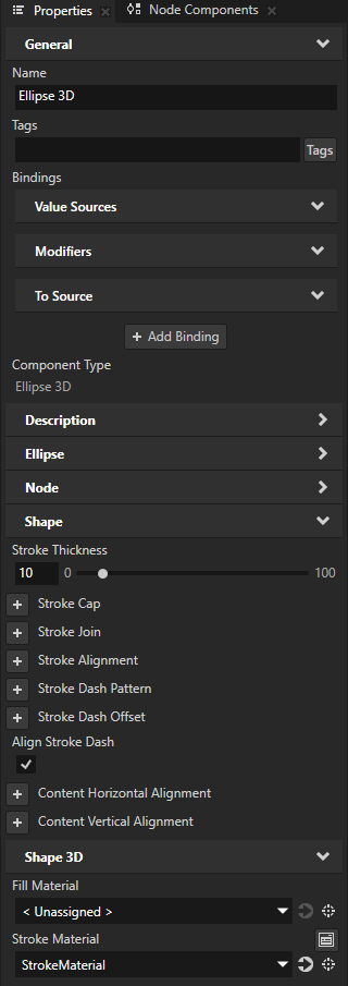
In the Properties, add and set:
Stroke Material to the material that you created
Stroke Thickness to the width that you want for the outline of the shape
(Optional) Fill Material to the material that you want to use to fill the shape
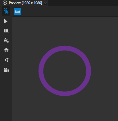
To draw the shape using only the stroke and no fill, set Fill Material to < Unassigned >.
Setting dashed stroke
To set a dashed stroke:
Create or select a shape node that uses stroke.
For example, in the Node Tree, create a Rectangle 2D node and set its stroke. See Using the Rectangle nodes.
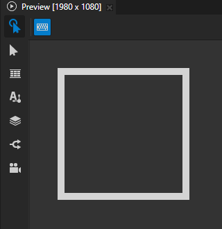
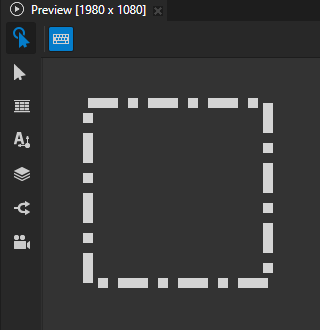
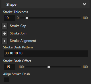
In the Properties, add and set the Stroke Dash Pattern property to set the length of the alternating dashes and gaps in the stroke.
Enter a list of values separated by spaces or commas, where the first value is the length of a dash and the second value is the length of a gap.
If you enter an odd number of values, Kanzi Shapes repeats the list to yield an even number of values.
Stroke Dash Pattern
Result
5
10 5
20 5 10 5
20 5 5 5 5 5
Kanzi Shapes by default scales the dash pattern to fit such that it repeats at least once and always in multiples of the complete pattern. The center of the first dash is aligned to the corners and end points of the shape.
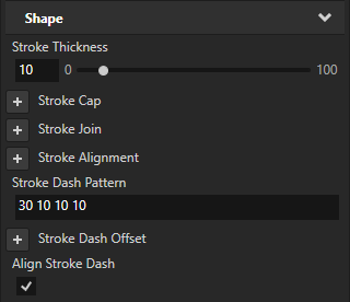

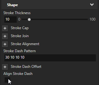
(Optional) To not scale and align the dash pattern, in the Properties, disable the Align Stroke Dash property.
(Optional) To define the position along the SVG path where the dash of the stroke begins, in the Properties, add and set the Stroke Dash Offset property.

Setting the shape of the stroke at the ends of a path
You can use the Stroke Cap property to set the shape of the stroke at the ends of a path. For example, in a dashed stroke the shape that you set is visible at the ends of each dash.
To set the shape of the stroke at the ends of a path:
Create or select a shape node that uses stroke and shows a shape with open paths.
For example, in the Node Tree, create a Line 2D node and set its stroke. See Using the Line nodes.
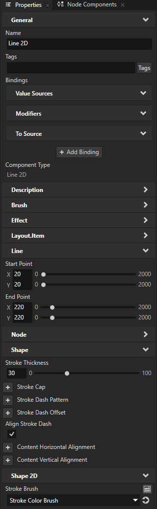
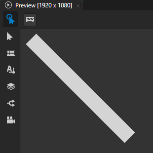
In the Properties, add and set the Stroke Cap property to:
Butt to not extend the stroke beyond its endpoints.
This is the default value.

Rectangle to extend the stroke by a rectangle whose width is half of the stroke thickness.

Round to extend the stroke by a half circle whose diameter is equal to the stroke thickness.

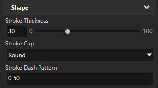
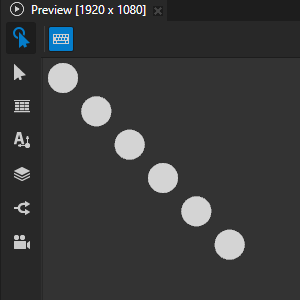
For example, to turn a thick stroke into a series of circles, set:
Stroke Cap to Round
Stroke Dash Pattern to 0 followed by the distance that you want between the centers of the circles
Setting the shape of corners
You can use the Stroke Join property to set the shape of the corner that is formed when the ends of two strokes meet or overlap.
To set the shape of the corners in a shape:
Create or select a shape node that uses stroke and shows a shape with sharp corners.
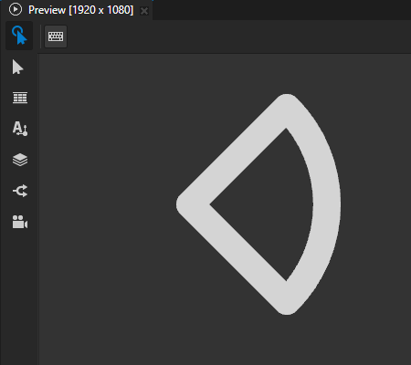
For example, in the Node Tree, create an Ellipse 2D node that draws the outline of a circle sector. See Using the Ellipse nodes.
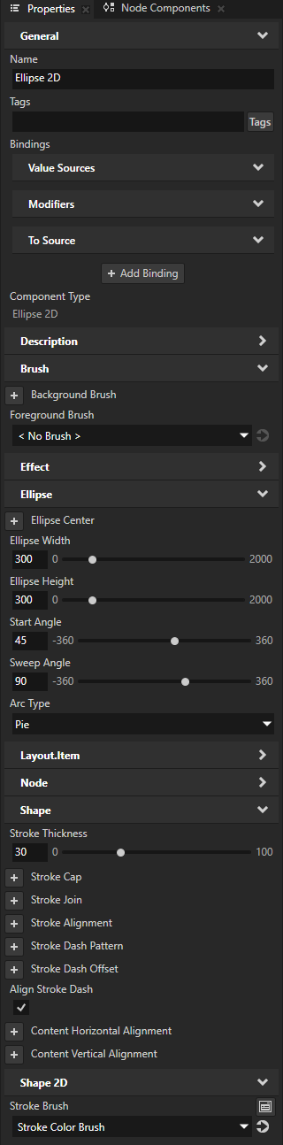
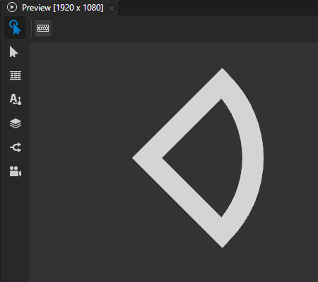
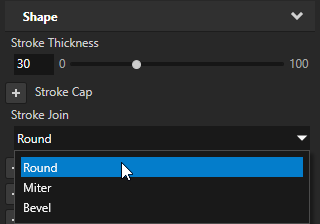
In the Properties, add the Stroke Join property and set it to:
Miter to use a sharp corner.
This is the default value.

Round to use a round corner.

Bevel to use a bevelled corner.

(Optional) When two line segments meet at a sharp angle, the miter can extend far beyond the thickness of the stroke. You can use the Stroke Miter Limit property to set a limit on the ratio of the miter length to the Stroke Thickness. When the limit is exceeded, Kanzi converts the join to a bevelled join.
Setting the alignment of the stroke
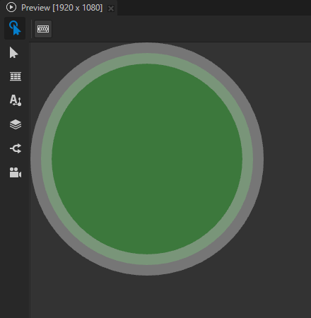
You can use the Stroke Alignment property to align the stroke in a closed path to the inside or outside of the shape boundary. Closed paths use center alignment by default. Open paths always use center alignment.
When you align the stroke so that it is inside or outside the shape boundary, the value of the Fill Rule property can affect the result. The Fill Rule property determines which regions in a shape are inside and which regions are outside. See Setting the fill rule.
To set the alignment of the stroke:
Create or select a shape node that uses stroke and shows a shape with closed paths.
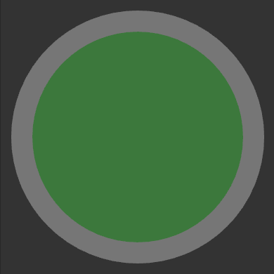
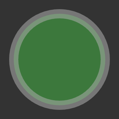
For example, in the Node Tree, create an Ellipse 2D node that draws the translucent outline of a filled circle. See Using the Ellipse nodes.
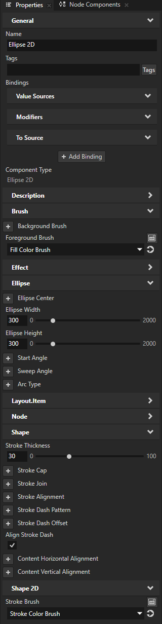
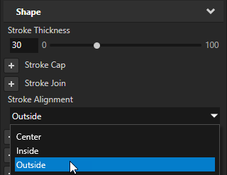
In the Properties, add and set the Stroke Alignment property to:
Center to align the centerline of the stroke to the path.
This is the default value.
Inside to align the outer edge of the stroke to the shape boundary, so that the stroke is inside the shape boundary.
The value of the Fill Rule property can affect the result.
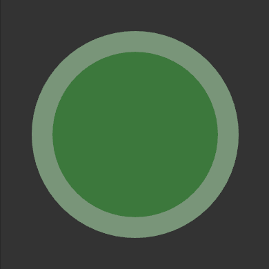
Outside to align the inner edge of the stroke to the shape boundary, so that the stroke is inside the shape boundary.
The value of the Fill Rule property can affect the result.