Adding shadows to Prism render graphs
These steps show how to add different shadow types to Prism render graphs and how to define which objects cast shadows.
For an introduction to Prism graphs, see Prism graphs for a walkthrough on creating a basic Prism graph first.
Scene setup
Creating a basic scene where shadows can be tested.
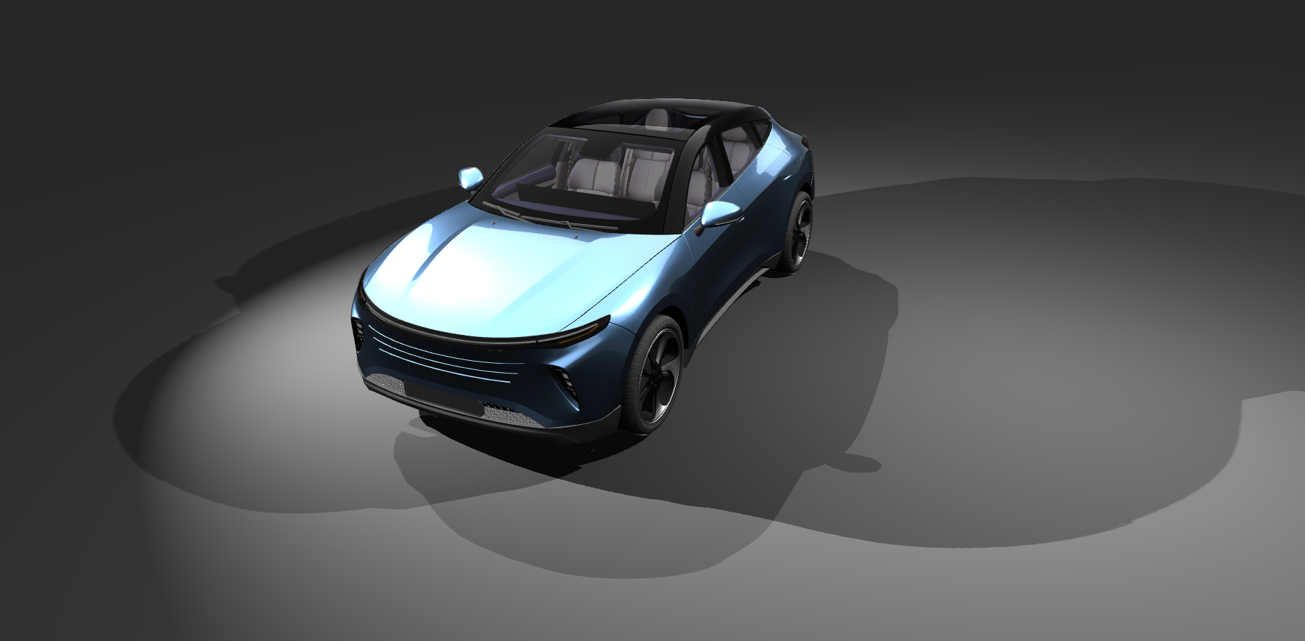
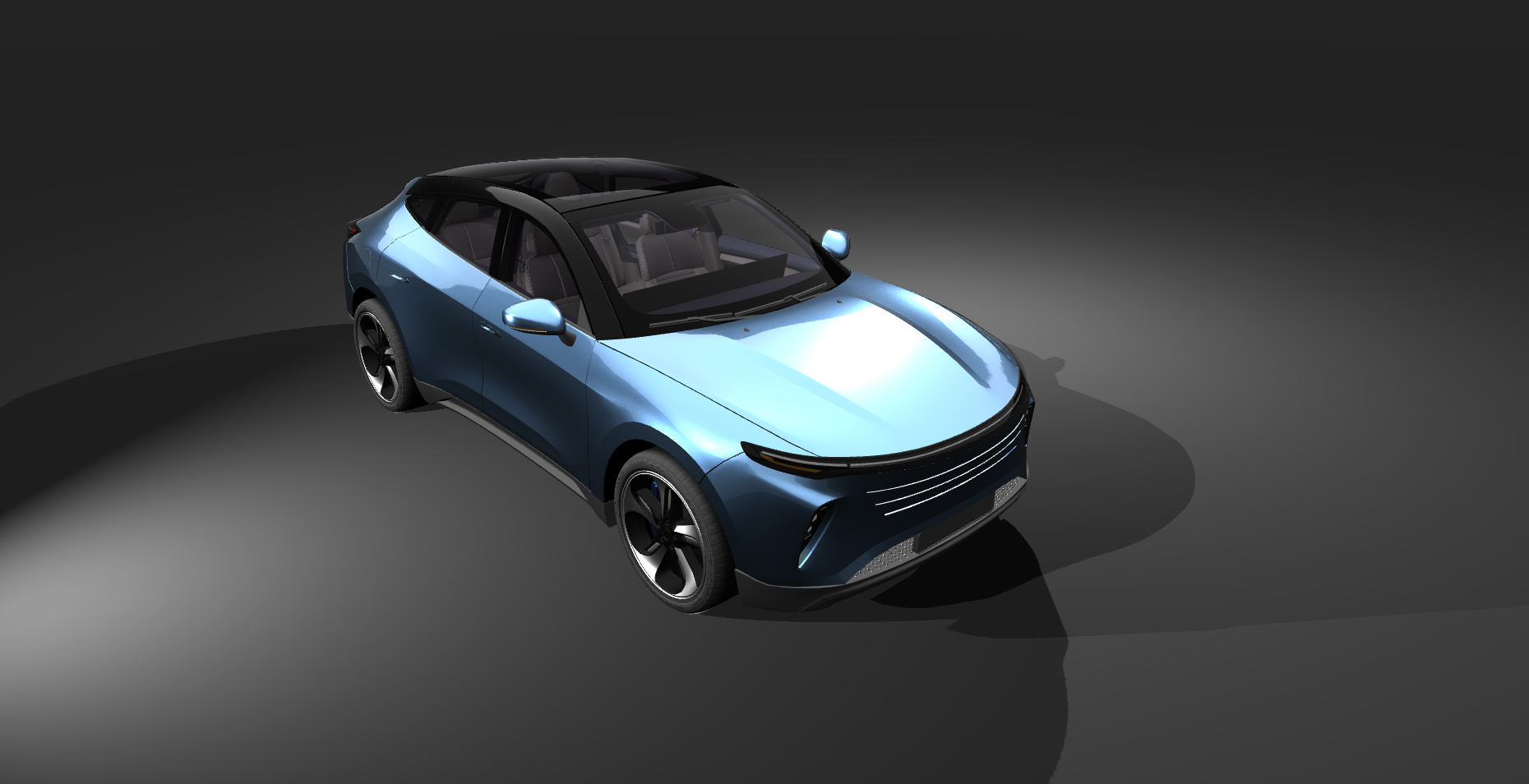
Add objects you want to cast shadows into the scene.
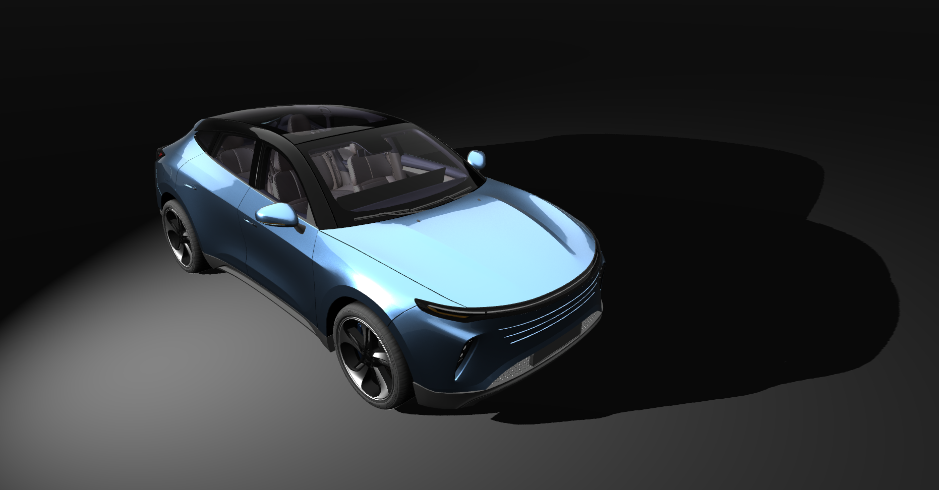
This example uses a ground box and a car model from the Kanzi Studio Asset Toolkit package. You can follow along with any objects you have.
Navigate to Asset Packages and select Asset Toolkit > Car from the asset browsing view. Use your mouse to drag and drop the car model into your scene.
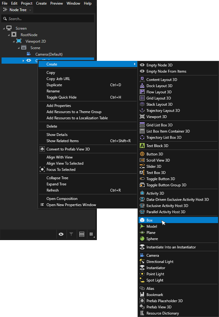
Add a ground box to the scene by right clicking on Scene > Create > Box.
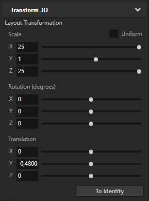
Use the Transform 3D property in the Properties panel to adjust the position and scale of the box.
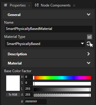
Select the ground box from the scene. In the Properties, go to the Mesh Material property and click the Navigate to selected item button to highlight the material of the model.
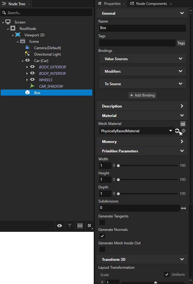
Switch the material type to SmartPhysicallyBased by selecting it from the Material Type dropdown menu.
This switches the material to use Smart Physically Based Material type, which is the easiest way to use shadows. Smart materials make it easy to enable or disable shader features on demand. To learn more about smart materials, see Using smart materials.
Note
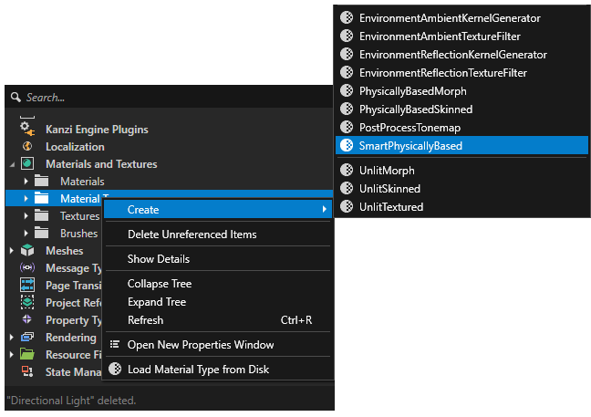
If you do not already have Smart Physically Based Material type in your project, you can create one by right-clicking in the Library > Materials and Textures > Material Types and selecting Create > Material Type > SmartPhysicallyBased.
Creating a new material type will automatically also add a matching material to the project. Use that material on the ground box.
Shadow material properties
The material type does not have shadow features enabled by default. The shaders must be enabled to support each shadow type.
Click Navigate to selected item on the Material Type field to select the SmartPhysicallyBasedMaterial type in the Library.
Click the Add Properties button on the bottom-right corner of the Properties menu. Enable Shadow for Directional Light, Shadow for Point Light, and Shadow for Spot Light.
The smart materials are now ready to receive shadows.
Tip
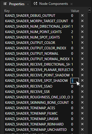
When the project does not use smart materials, enabling shadows on custom materials requires setting preprocessor definitions in the material.
Open the Material Type and scroll down to the Preprocessor Definitions section. Enable KANZI_SHADER_RECEIVE_SPOT_SHADOW, KANZI_SHADER_RECEIVE_POINT_SHADOW, and KANZI_SHADER_RECEIVE_DIRECTIONAL_SHADOW by setting their values to 1.
This enables each corresponding shadow type on the material.
Creating a Prism graph
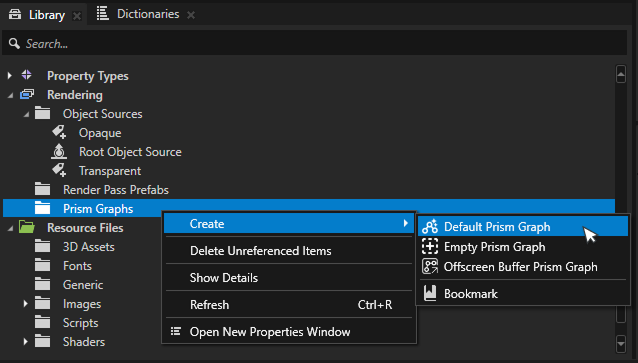
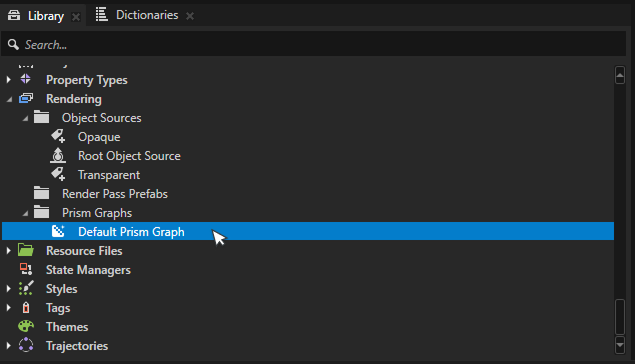
Go to Library > Rendering > Prism Graphs.
Right-click the Prism Graphs folder and select Create > Default Prism Graph.
Default Prism graph is a great starting point for most render graphs.
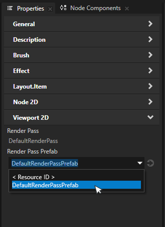
Select the Viewport 2D to render with the graph. From the viewport Properties, find the Render Pass Prefab property and select the created Prism graph from the dropdown.
The rendering may look the same as before, but the created Prism graph is now in use.
Spot shadows
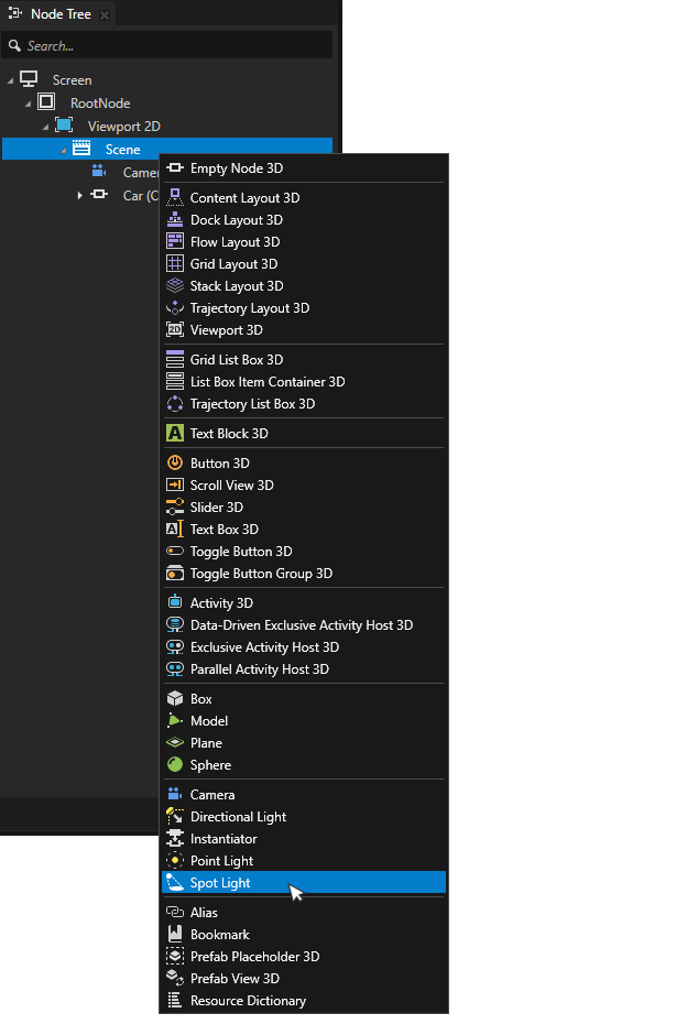
On the scene object, hold down Alt and right-click to open object creation menu. Select Spot Light to create a new spotlight. Move the spotlight to a position where it lights an object to cast shadows.
Open the Prism graph by double-clicking it in the Library.
Add a new Generate Shadow Map node to the graph. Select the spot light from the Light dropdown.
Add the Spot Shadow Map property to the Multi-Draw node by clicking the + icon and selecting Shadows > Spot Shadow Map.
Connect the output socket of the Generate Shadow Map node, to the Spot Shadow Map socket of the Multi-Draw node.
The graph is now complete and objects should cast spot shadows.
Adjusting shadow contact point
Sometimes shadows may appear to float slightly above the surface. Shadows have near and far plane settings that define the depth range of the shadow map. Both of these settings affect how shadows align with the surface.
These settings can be adjusted by adding Camera Near, Camera Far, and Shadow Bias properties to the light source.
Tip
A common issue is shadow acne, where shadows appear speckled or have artifacts. This is often due to precision issues in the shadow map. Adding Spot Shadow Bias, Point Shadow Bias, or Directional Shadow Bias to the corresponding light type can help.
Adjusting shadow resolution
Shadow map resolution can be adjusted in Prism editor.
Click the + icon on the Generate Shadow Map node and add the Width and Height properties and adjust the values.
Increasing the resolution improves shadow quality at the cost of performance.
Point shadows
Point shadows are largely similar to spot shadows, but they cast shadows in all directions from a point in space.
In Kanzi, the main difference is how shadow map resolution is set up in the Prism graph.
Hold down Alt and right-click on Scene. Select Point Light.
Open the Prism graph by double-clicking it in the Library.
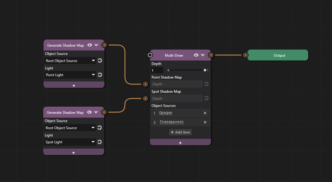
Add a new Generate Shadow Map node to the graph and add a Point Shadow Map property to the Multi-Draw node.
The Point Shadow Map node composites a given cubemap depth into the Multi-Draw pass. It expects a cubemap depth texture as input to its socket.
Connect the Generate Shadow Map node’s output socket to the Multi-Draw node’s Point Shadow Map socket.
Select the point light from the Light dropdown.
The light must be Point Light type for point shadows to work.
Similar to spot shadows, Camera Near, Camera Far, and Shadow Bias properties can be added to the light source to adjust shadow appearance. See Adjusting shadow contact point for more details.
The Prism graph is now complete and objects should cast point shadows.
Increasing point light shadow resolution
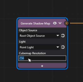
The resolution can be increased from the Generate Shadow Map node properties if the default resolution needs adjusting.
Click the + icon on the Generate Shadow Map node and add the Cubemap Resolution property.
Increase the resolution to a higher value, such as 256, to increase the shadow quality.
Note that higher resolution shadows may impact performance.
Directional shadows
Directional shadows are often used to simulate sunlight or other distant light sources.
The process is similar to other shadow types, but directional shadows require additional properties to define the shadow area.
Right-click on Scene and select Create > Directional Light.
Select the light and click the Add Properties button on the bottom-right of the Properties panel. Add the Z Far, Z Near, and Orthographic Plane Size properties to it.
These properties define the area where shadows are rendered. Adjust these values to cover the area where shadows are needed. Orthographic Plane Size defines the size of the shadow casting area, while Z Near and Z Far define the depth range.
After configuring the light properties, set up the shadow map in the Prism graph.
Open the Prism graph by double-clicking it in the Library.
Add a new Generate Shadow Map node to the graph and add a Directional Shadow Map property to the Multi-Draw node.
Connect the output socket of the Generate Shadow Map node to the Directional Shadow Map socket of the Multi-Draw node.
Select the directional light from the Light dropdown.
The light must be Directional Light type for directional shadows to work.
See Adjusting shadow resolution to learn how to adjust shadow resolution.
The graph is now complete.
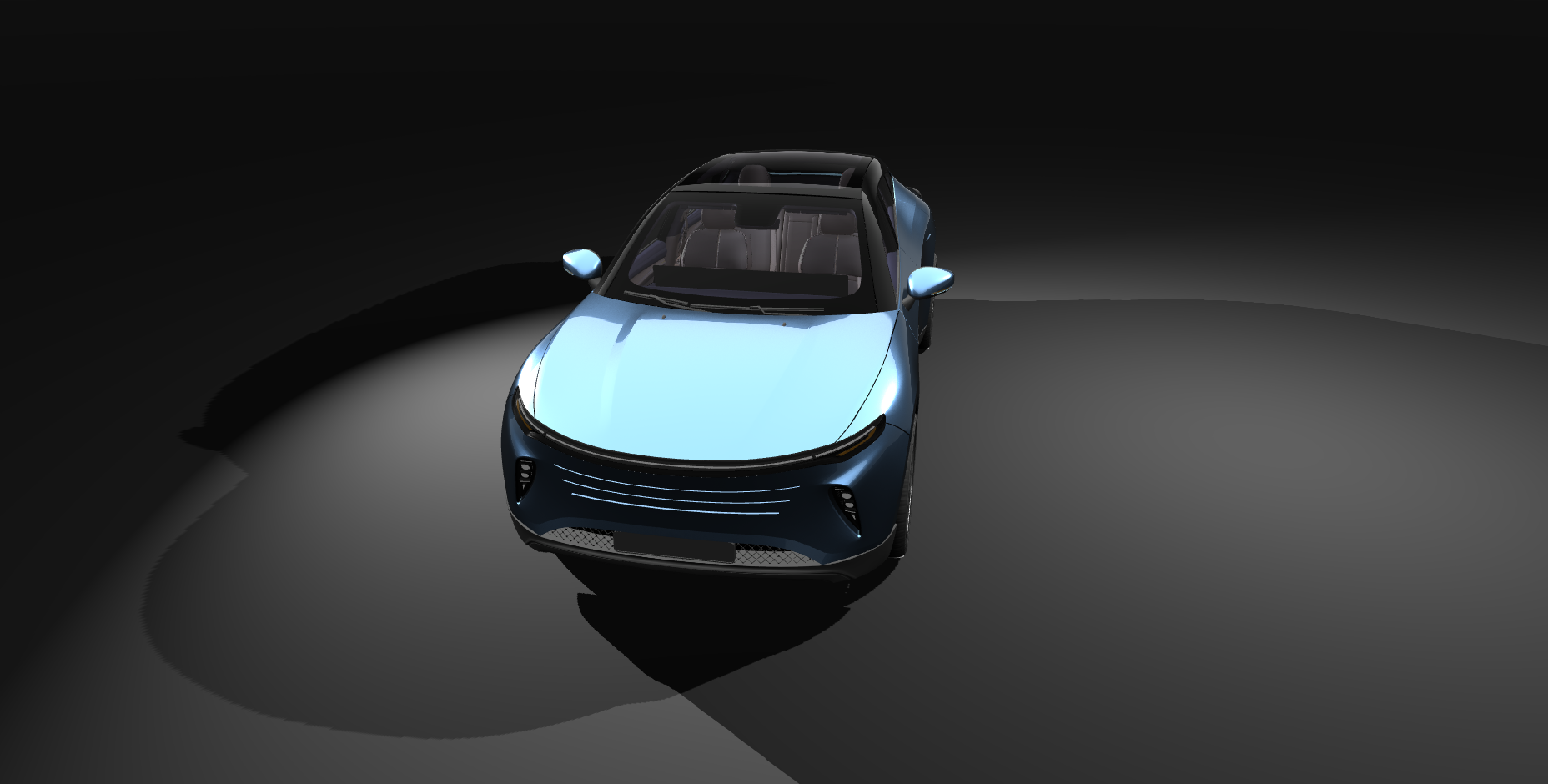
The final Prism graph with all three shadow types configured looks like this:
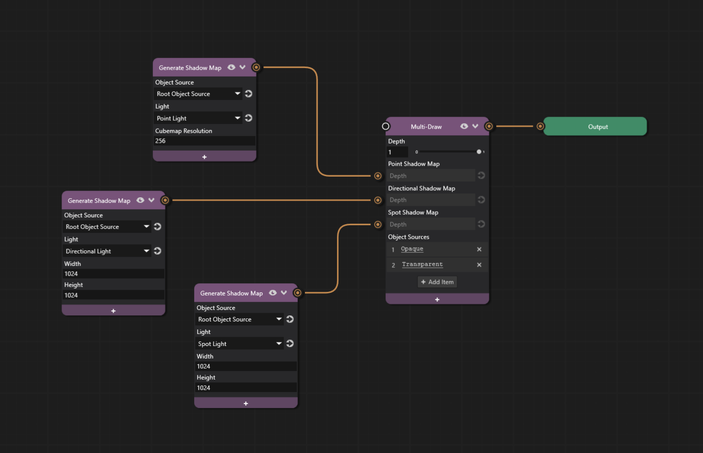
All shadow types should now be visible in the scene.