Using the Structure Renderer node
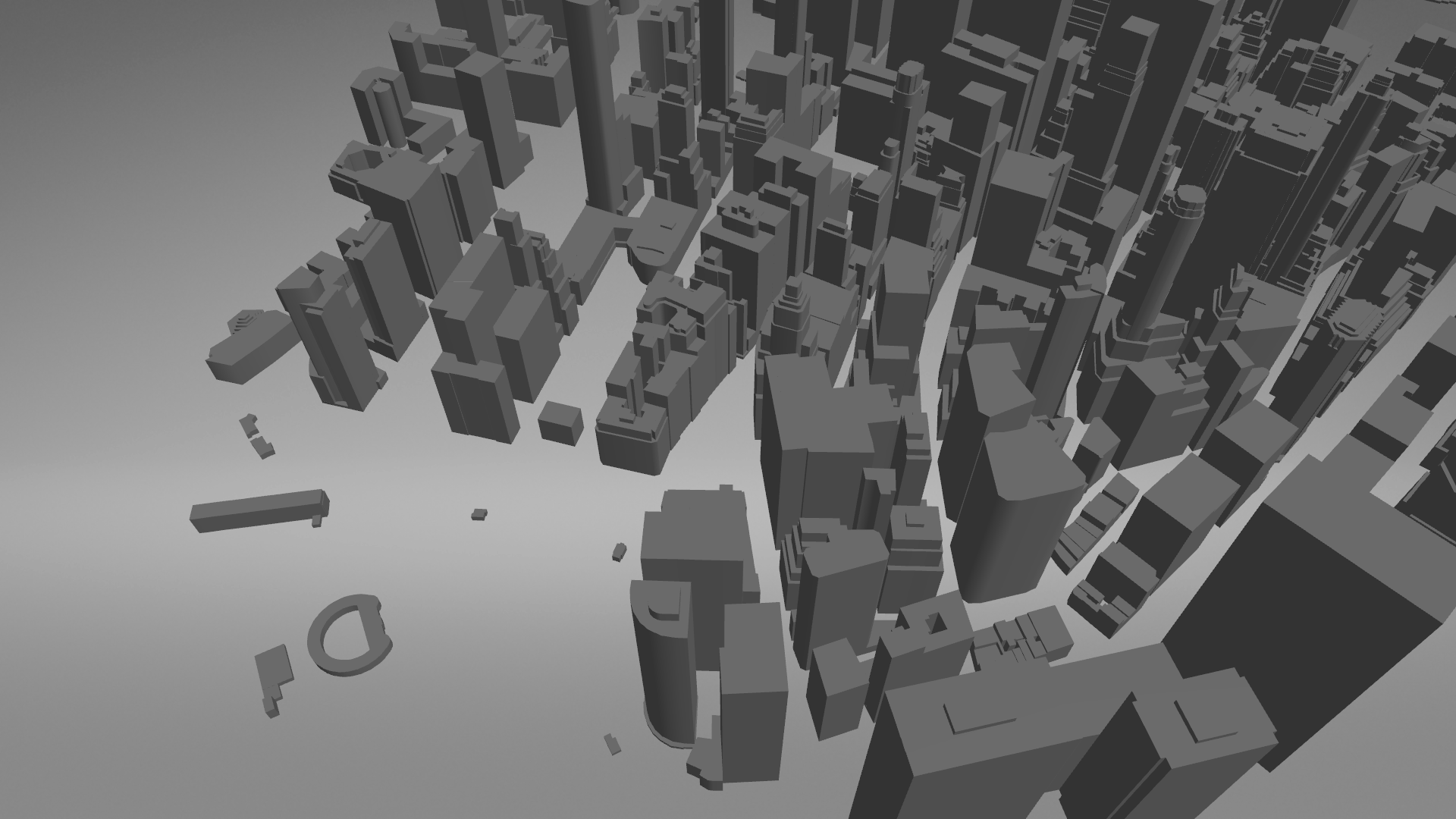
Use the Structure Renderer node to render structures, such as 3D buildings and landmarks. The Structure Renderer renders extruded 2D polygons and 3D meshes.
For planar input geometry, such as 2D polygons and 2D triangle lists, the Structure Renderer extrudes the geometry with an optional roof.
The Structure Renderer can also render textured 3D mesh input geometry, but in that case the properties related to extrusion and UVs have no effect, because they exist in the input geometry.
You can also use the Structure Renderer to inverse extrude polygons. This means that you can use the Structure Renderer with negative height values. This is useful, for example, when you create water areas that have lower elevation than the rest of the map. By inverse extruding water polygons, the Structure Renderer creates the floor of the water and walls that you can texture as ground. For this, you need to set the Disable Tile Clipping property to disabled. Otherwise the Structure Renderer renders walls at tile boundaries.
In addition to the kzPosition and kzNormal vertex attributes, the Structure Renderer supports also the kzTextureCoordinate0 attribute.
In case of extruded 2D geometry, the Structure Renderer generates UVs as follows:
Roof UVs: similarly to the Area Renderer node with the exception that you can optionally orient the roof UVs along the longest edge of the roof polygon.
Wall U: As a wall run length, which starts from the first polygon vertex, and can restart at the smoothing group border. You can normalize the run length to values from 0 to 1, or actual run length in projected meters, depending on UV mode.
Wall V: 0 for floor level and 1 for roof in normalized mode, or floor and roof height in projected meters, respectively.
Creating a Structure Renderer using the Palette
This section explains how to use the Kanzi Maps Palette to quickly create and set up a Structure Renderer node that renders 3D buildings. To learn how to create and set up a Structure Renderer manually, see Creating a Structure Renderer manually.
To create a Structure Renderer using the Palette:
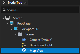
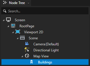
In the Node Tree, select the Map View node where you want to render 3D buildings.
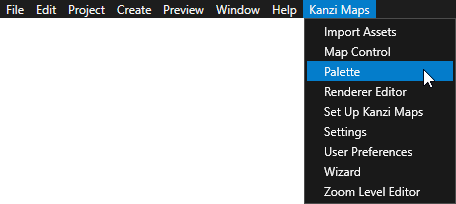
In the Kanzi Studio main menu, select Kanzi Maps > Palette.
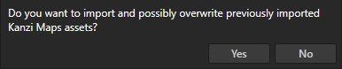
When Kanzi Studio asks whether you want to import assets, click Yes.
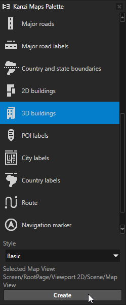
In the Kanzi Maps Palette:
Select 3D Buildings.
(Optional) If you want to render buildings with textured materials, set the Style to Textured.
Click Create.
In the Confirm modifications dialog, click Apply Modifications to let Kanzi Studio modify your project as needed to render the content that you selected.
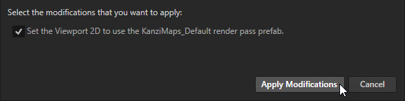
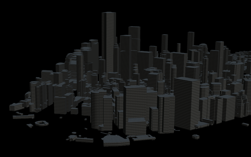
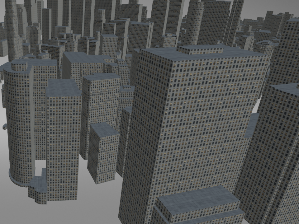
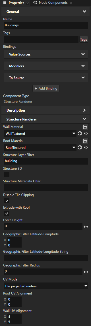
Kanzi Studio creates in the Map View node a Structure Renderer node named Buildings, which renders 3D buildings. If you selected the textured style, the Renderer applies textured materials to the walls and roofs of the buildings.
Creating a Structure Renderer manually
This section explains how you can create and set up a Structure Renderer manually to render 3D buildings. To learn how to use the Kanzi Maps Palette to quickly render buildings, see Creating a Structure Renderer using the Palette.
Creating a Structure Renderer that renders 3D buildings
To create a Structure Renderer that renders 3D buildings:
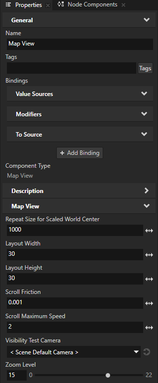
In the Node Tree, select a Map View node. In the Properties, set the Zoom Level property to 15.
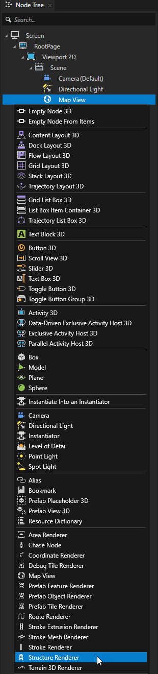
In the Map View node, create a Structure Renderer node and name it Buildings.
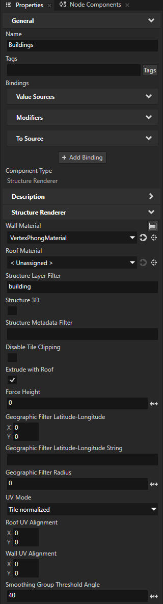
In the Properties, set:
Wall Material to the material that you want to use to set the appearance of the building walls.
To learn how to use a textured material, see Creating a Structure Renderer that renders 3D buildings with textured materials.
Roof Material to the material that you want to use to set the appearance of the building roofs.
When you leave the Roof Material property set to < Unassigned>, Kanzi Maps renders the roofs using the material that you set with the Wall Material property.
Structure Layer Filter to the name of the layer from which you want to get the map feature that you render.
For example, if you use Mapbox, set Structure Layer Filter to building. See Supported backends.
Tip
You can use the Renderer Editor to set layer and metadata filters. See Using the Renderer Editor.
Smoothing Group Threshold Angle to 40.
This way, you set the allowed angle difference between smooth and non-smooth normal, below which Kanzi Maps uses non-smooth normal. A threshold angle larger than 90 degrees makes all vertices smooth.
Creating a Structure Renderer that renders 3D buildings with textured materials
To create a Structure Renderer that renders 3D buildings with textured materials:
Use the Structure Renderer node to render buildings. See Creating a Structure Renderer that renders 3D buildings.
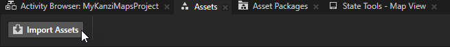
In the Assets, click Import Assets and import the texture images that you want to use to set the appearance of the roofs and walls of the buildings.
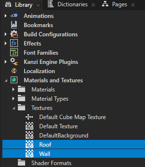
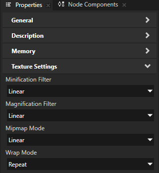
In the Library > Materials and Textures > Textures, select the textures that you imported. In the Properties, set:
Mipmap Mode to Linear
Wrap Mode to Repeat
This way, you set the textures to repeat to cover the geometry.
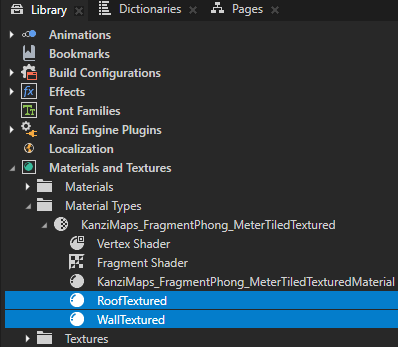
In the Library, right-click Materials and Textures and select Load Material Type from Disk. Go to
<KanziWorkspace>/Engine/plugins/maps/assets/MaterialTypesand load theKanziMaps_FragmentPhong_MeterTiledTextured.kzmatfile.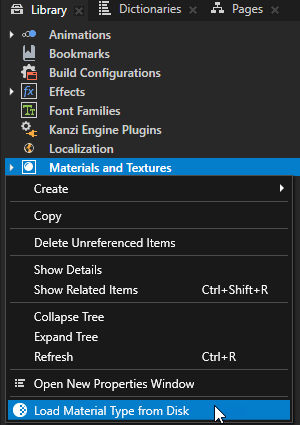
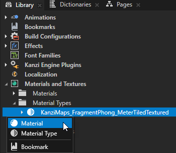
In the Library > Materials and Textures > Material Types, press Alt and right-click KanziMaps_FragmentPhong_MeterTiledTextured, and select Material. Create two materials, one for the walls and one for the roofs.
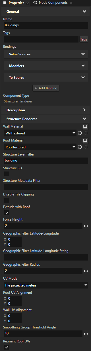
In the Node Tree, select the Structure Renderer node that renders the buildings. In the Properties, set:
Wall Material and Roof Material to the textured materials that you created for the walls and roofs
UV Mode to Tile projected meters
This sets the Structure Renderer node to generate UVs in projected meters across a tile.
Reorient Roof UVs to enabled
This orients the roof UVs of each building along the longest edge of the roof of that building.
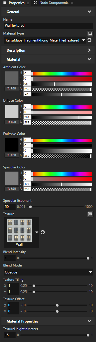
In the Library > Materials and Textures > Materials, select the material that you created for the walls. In the Properties, set:
Texture to the texture that you want to use for that material.
TextureHeightInMeters to the height in meters that you want the texture image to represent.
Repeat the previous step for the material that you created for the roofs.

In the Node Tree, select the Structure Renderer node. In the Properties, set the Wall UV Alignment property:
Y property field to the height in meters to which you want to map one floor of a building.
For example, if your wall texture shows three rows of windows, set the Wall UV Alignment Y to one third of the value of the TextureHeightInMeters property that you set in the wall material.
This way, you align the windows correctly along the roof and ground.
X to the width in meters to which you want to map the distance between two windows.
This way, you align the windows correctly along the corners of the buildings.
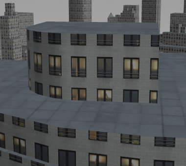
Without wall UV alignment:
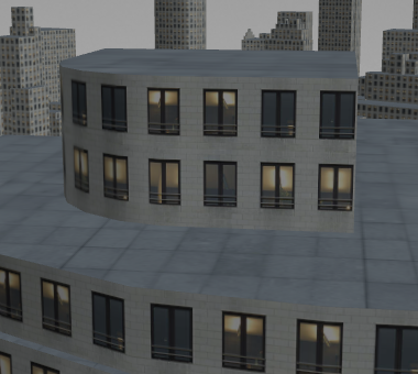
With wall UV alignment:
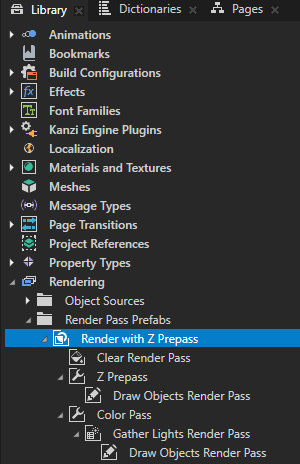
In the Preview, when you click and drag the left mouse button to pan the map, you can see flickering and popping in the wall textures. This is caused by overdraw issues related to z-fighting. To fix the rendering, use a render pass prefab that does a depth prepass.
For example:
In the Library > Rendering > Render Pass Prefabs, create a Group Render Pass.
Set the Viewport 2D node to use the render pass prefab that you created.
In the render pass prefab that you created, create:
Pipeline State Render Pass named Z Prepass. In the Properties, add and set the Color Write Mode to None.
In the Z Prepass render pass, create a Draw Objects Render Pass that draws the buildings. In the Properties, add and set the Camera to a depth camera whose Z Far property you set to slightly less than the Z Far property of the default camera. For example, use 100 for the default camera and 99 for the depth camera.
Pipeline State Render Pass named Color Pass. In the Properties, add and set:
Depth Test Function to Less
Depth Write Enabled to disabled
In the Color Pass render pass, create a Draw Objects Render Pass that draws the buildings.
Filtering map features based on location
You can use these Structure Renderer properties to filter map features based on their location:
Geographic Filter Latitude-Longitude sets the latitude-longitude coordinates of the center location for geographic filtering.
Geographic Filter Radius sets the radius of the area to render. Specify the radius in projected meters.
Controlling the visibility of content based on zoom level
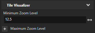
To avoid visual clutter in your map, you can show content only at a specific range of zoom levels. Use the Minimum Zoom Level and Maximum Zoom Level properties to set the range of zoom levels at which a tile-based Renderer renders its content.
For example, in the Node Tree, select a Renderer node. In the Properties, add and set the Minimum Zoom Level property to 12.5.
This way, you hide the content rendered by the Renderer when in the Map View node the value of the Zoom Level property is less than 12.5.
Clipping geometry to the boundaries of map tiles
The Disable Tile Clipping property sets whether the Structure Renderer node clips geometry to the boundaries of map tiles. By default, the Structure Renderer node clips the geometry.
If overlapping geometry on tile boundaries is not an issue with the material that you use, you can disable clipping by setting the Disable Tile Clipping property to enabled. This can reduce tile processing time.