Using 3D shape nodes
Use 3D shape nodes to draw vector shapes in 3D space.
These 3D shape nodes are available in Kanzi Shapes:
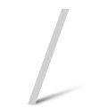
Line 3D node to draw straight lines. See Using the Line nodes.
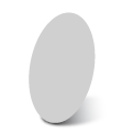
Oval 3D node to draw arcs, ellipses, circles, circle sectors, and segments. See Using the Oval nodes.
Path 3D node to draw arbitrary shapes. See Using the Path nodes.

Rectangle 3D node to draw rectangles. See Using the Rectangle nodes.
Composite Shape 3D node to combine 3D shape nodes using Boolean operations on the geometry of the nodes. See Using the Composite Shape nodes.

Filling a 3D shape node
Use a material to fill the shape in a 3D shape node.
To fill a 3D shape:
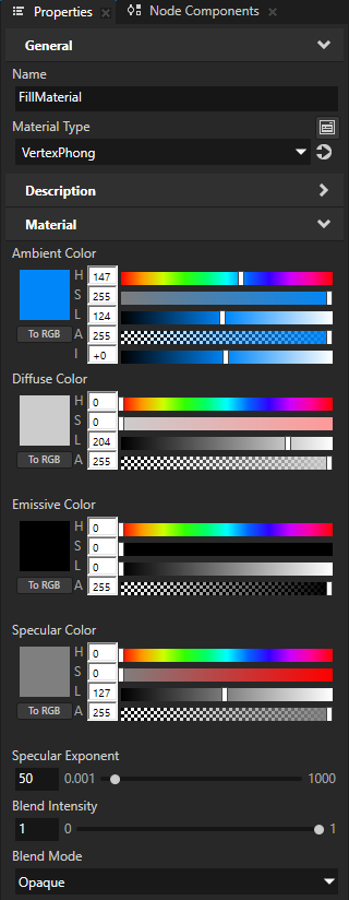
In the Library > Materials and Textures create the material that you want to use to fill a 3D shape node.
For example, create a material that uses the VertexPhong material type.
Tip
If your project does not contain the VertexPhong material type, in the Library > Materials and Textures press Alt and right-click Material Types, and select VertexPhong.
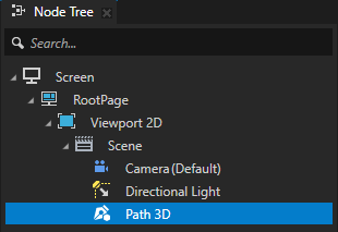
Create or select a 3D shape node that you want to fill.
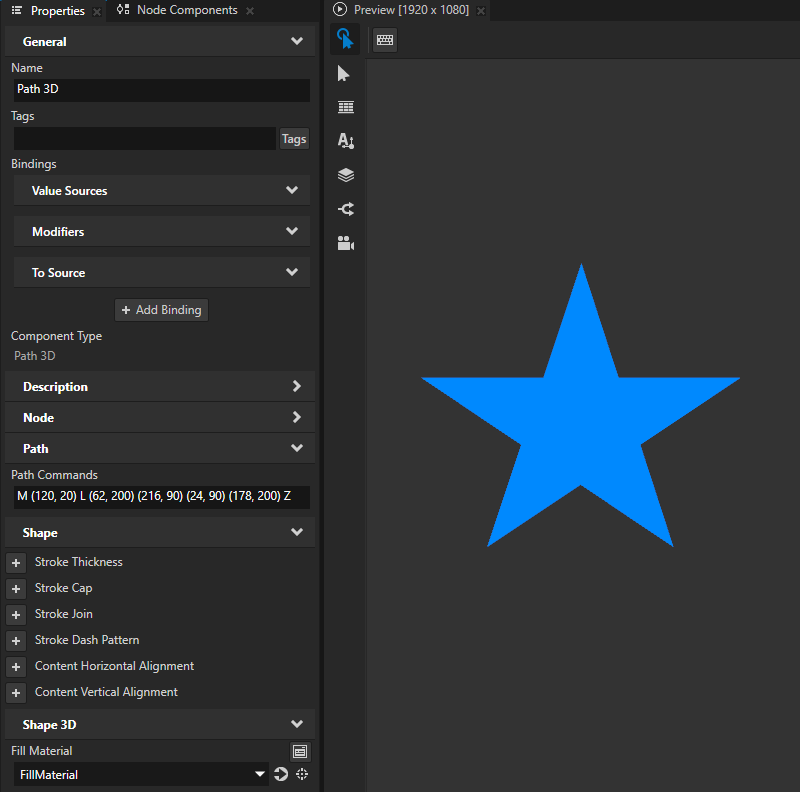
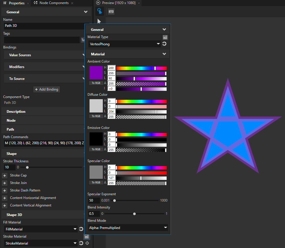
For example, in the Node Tree create a Path 3D node and in the Properties set the Path Commands property to
M (120, 20) L (62, 200) (216, 90) (24, 90) (178, 200) Z
When you create a closed 3D shape, that shape by default has a black fill and no stroke.
In the Properties add the Fill Material property and set it to the material that you created.
(Optional) To set the appearance of the outline of the 3D shape, add and set the Stroke Material and Stroke Thickness properties. See Using stroke.
Kanzi renders the outline on top of the fill and blends the two materials.
Setting the stroke of a 3D shape
To set the style of the stroke of a 3D shape:
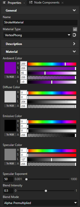
In the Library > Materials and Textures create the material that you want to use to define the appearance of a line or outline of a shape.
For example, create a material that uses the VertexPhong material type.
Tip
If your project does not contain the VertexPhong material type, in the Library > Materials and Textures press Alt and right-click Material Types, and select VertexPhong.
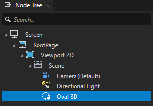
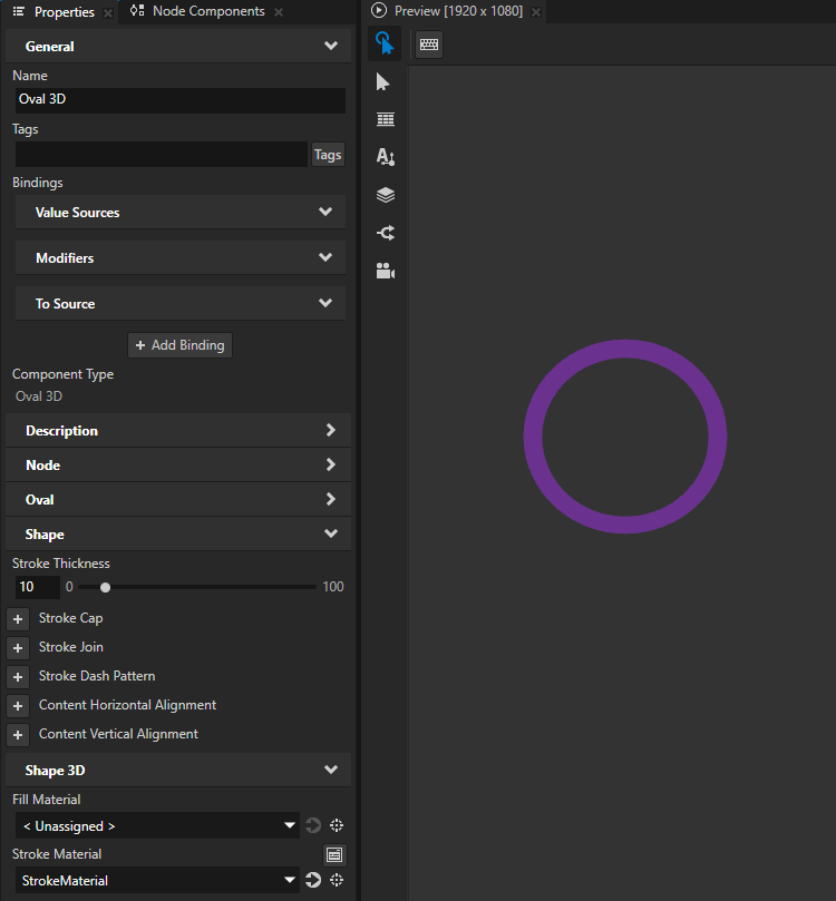
Create or select a 3D shape node whose stroke you want to set.
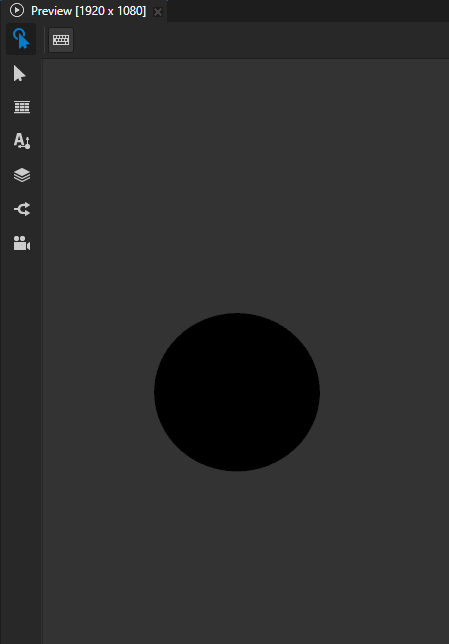
For example, in the Node Tree create an Oval 3D node.
When you create a closed 3D shape, that shape by default has a black fill and no stroke.
In the Properties add and set:
Stroke Material to the material that you created
Stroke Thickness to the width that you want for the outline of the shape
(Optional) Fill Material to the material that you want to use to fill the shape
To draw the shape using only the stroke and no fill, set Fill Material to < Unassigned >.
Rendering depth in 3D shape nodes
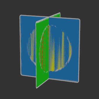
When you position two shapes so that they are coplanar and overlap, the depth buffer cannot figure out which shape is in front of the other shape. This phenomenon, called z-fighting, leads to a visual artifact where the shapes seem to be switching order, creating glitchy patterns.
To handle z-fighting, Kanzi Shapes by default renders 3D shape nodes in two passes:
Renders the depth buffer without using depth offset.
Renders the color buffer using the depth offset for testing.
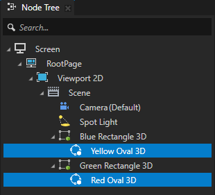
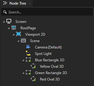
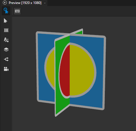
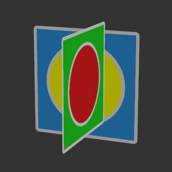
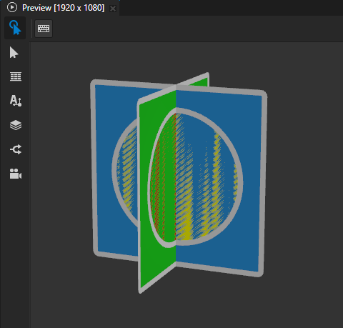
For example, Kanzi Shapes renders the depth in these intersecting shapes correctly:
A Rectangle 3D node that has blue fill and contains an Oval 3D node that has yellow fill.
A Rectangle 3D node that has green fill, is rotated 90 degrees along the y axis, and contains an Oval 3D node that has red fill.
All four nodes have gray stroke.
Two-pass rendering means that Kanzi renders each shape twice, which causes performance overhead. When you do not need two-pass rendering, you can optimize performance by manually setting the depth rendering mode.
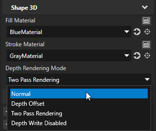
To set the depth rendering mode, select a 3D shape node and in the Properties, add and set the Shape 3D > Depth Rendering Mode property:
|
|
|
|
|
|
Setting the depth offset for the fill and stroke in 3D shape nodes
To improve rendering performance, instead of using the default two-pass rendering, you can manually set the depth offset for the fill and stroke of each 3D shape node.
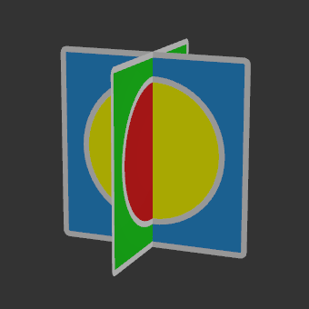
This example shows how to set the depth offset in these intersecting Rectangle 3D nodes:
To set the depth offset for the fill and stroke in 3D shape nodes:
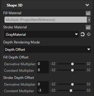
In the Node Tree, select the two intersecting Rectangle 3D nodes. In the Properties, add and set these Shape 3D properties:
Depth Rendering Mode to Depth Offset
With this mode, you set Kanzi Shapes to use the Fill Depth Offset and Stroke Depth Offset properties to apply a depth offset to the fill and stroke of a 3D shape node and its descendants.
Fill Depth Offset property Constant Multiplier property field to 0
The Constant Multiplier sets a multiplier for the smallest measurable unit of depth, dependent on the target platform.
Stroke Depth Offset property Constant Multiplier property field to -3
This way you set Kanzi Shapes to render in each rectangle the stroke over the fill.
When you use the Kanzi default render passes to render you content, a negative offset corresponds to a depth value closer to the camera.
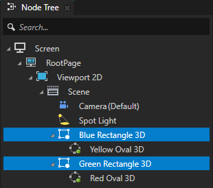
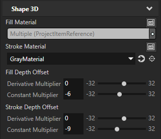
In the Node Tree, select the Oval 3D nodes that are children of the Rectangle 3D nodes. In the Properties, add and set:
Fill Depth Offset property Constant Multiplier property field to -6
Stroke Depth Offset property Constant Multiplier property field to -9
This way you set Kanzi Shapes to render the ovals over the rectangles, and the stroke of the ovals over the fill.