Using the Path nodes
Use the Path nodes to draw arbitrary shapes based on SVG 1.1 compliant path data. See https://www.w3.org/TR/SVG11/paths.html#PathData.
Drawing complex shapes
To draw complex shapes:
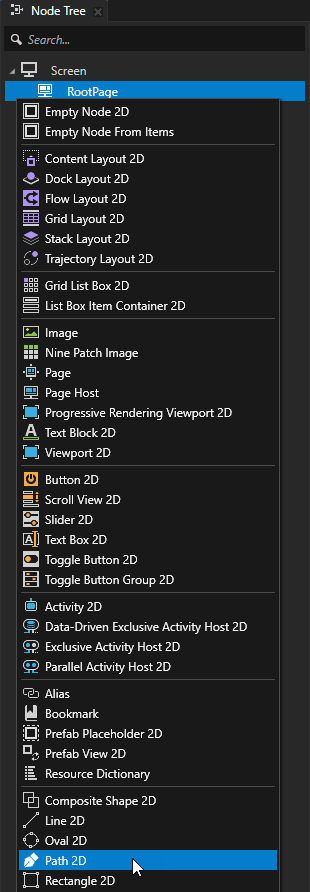
In the Node Tree or Prefabs press Alt and right-click the node where you want to create a Path node and select either Path 3D, or Path 2D.
Note that you can create a 3D node only inside 3D nodes, and a 2D node only inside 2D nodes.
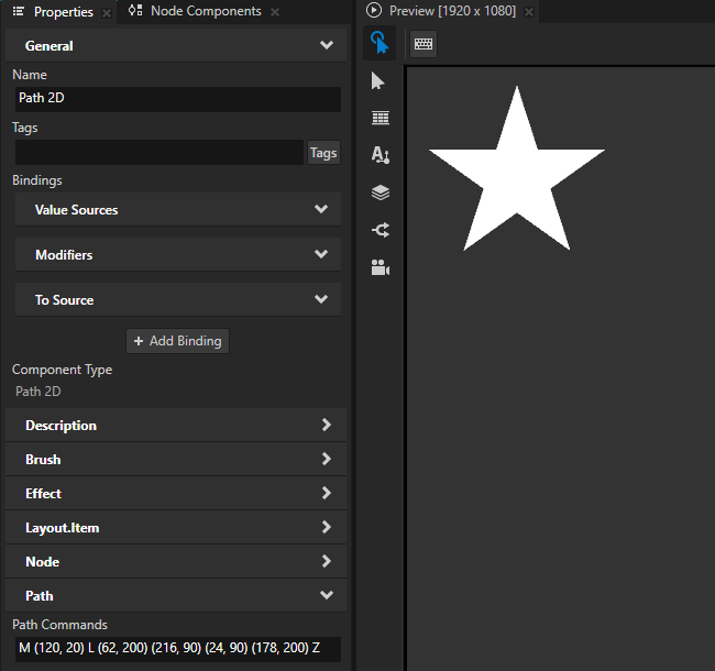
In the Properties set the value of the Path Commands property to the SVG path data that defines the shape that you want to draw.
For example, to draw a star, set Path Commands to
M (120, 20) L (62, 200) (216, 90) (24, 90) (178, 200) Z
where:
Mindicates amovetoinstruction which starts a new path at the coordinates x=120, y=20 relative to the top-left corner of the Path 2D node.Lstarts a series oflinetoinstructions that each draw a line from the current point to a given coordinate, which becomes the new current point.Zcloses the path by drawing a straight line from the current point to the initial point of the path.Uppercase letters indicate absolute coordinates within the Path 2D node. Use lowercase commands to indicate coordinates relative to the previous instruction.
Enclosing the coordinates in parentheses is optional and shown here to improve the readability of the commands.
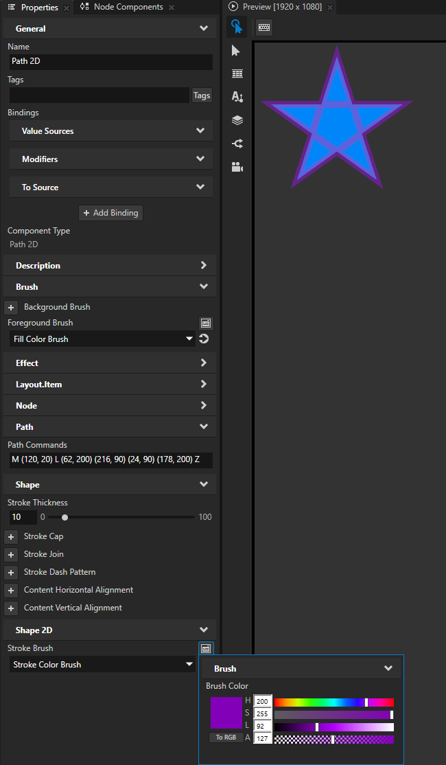
To set the appearance of the shape, set its fill and stroke. See Filling a shape and Using stroke.
Setting the input area for a Path 2D node
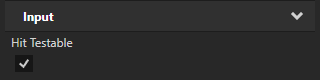
When you enable hit testing for a node with the Input > Hit Testable property, the entire area of that node receives input by default.
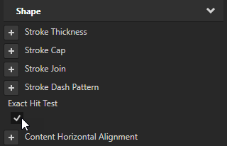
To make only the area formed by the composited geometry of the shapes in a 2D shape node receive input, in the Node Tree or Prefabs select that node and in the Properties add and enable the Shape > Exact Hit Test property.
To learn about handling user input in Kanzi, in the Kanzi framework documentation see Working with > Input.
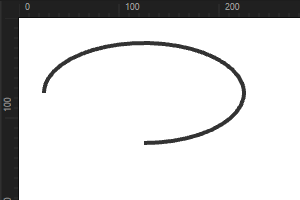
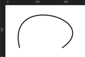
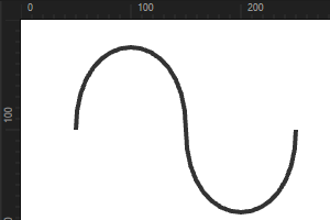
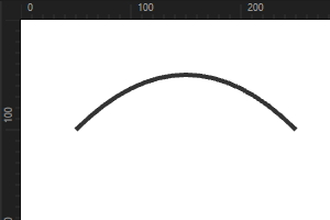
Examples of path commands
This table shows examples of path commands to draw lines and curves.
Shape |
Command |
Parameters |
Example Path Commands |
Result |
|---|---|---|---|---|
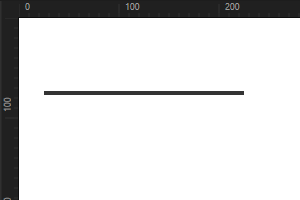
Horizontal line |
|
|
|
|
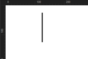
Vertical line |
|
|
|
|
Elliptical arc |
|
|
|
|
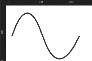
Cubic Bézier curve |
|
|
|
|
Smooth cubic Bézier curve |
|
|
|
|
Quadratic Bézier curve |
|
|
|
|
Smooth quadratic Bézier curve |
|
|
|
|