Tutorial: Navigation
In this tutorial, you learn how to add basic routing and navigation simulation to a map.
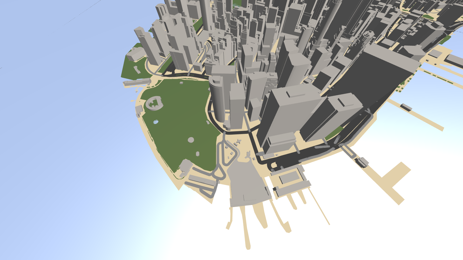
This video shows the result of the tutorial.
Assets for the tutorial
The starting point of this tutorial is the <KanziWorkspace>/Engine/plugins/maps/tutorials/AddingNavigation/Start/Tool_project/AddingNavigation.kzproj Kanzi Studio project.
You can find the completed tutorial in the <KanziWorkspace>/Engine/plugins/maps/tutorials/AddingNavigation/Completed directory.
In Kanzi Studio, to see the tutorial project in the Preview, in the main menu select Kanzi Maps > Set Up Kanzi Maps. This way, you copy the Kanzi Maps library files to the Application/bin directory of the tutorial project.
Create a route
In this section, you create a route manually without using the Kanzi Maps Palette.
When you use Kanzi Maps Palette to create a route, Kanzi Studio automatically creates the Route Renderer node, data sources, and default route required to render the route. In this tutorial, you learn how to add them manually.
To create a route:
In Kanzi Studio, open the
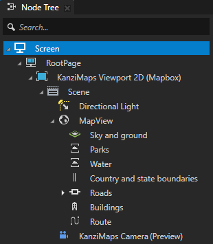
<KanziWorkspace>/Engine/plugins/maps/tutorials/AddingNavigation/Start/Tool_project/AddingNavigation.kzprojproject.The project contains a 3D map with Renderer nodes that render parks, water areas, roads, and 3D buildings.
In the Kanzi Studio main menu, select Kanzi Maps > Set Up Kanzi Maps.
This way, you copy the Kanzi Maps library files to the
Application/bindirectory of the tutorial project.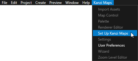
If Kanzi Studio asks whether you want to set the map plugin credentials, click Yes and set up your Mapbox credentials. See Setting up your Mapbox credentials.
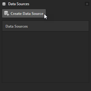
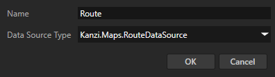
In the Data Sources window, click Create Data Source and set:
Name to Route
Data Source Type to Kanzi.Maps.RouteDataSource
The Route Data Source provides data about routes.
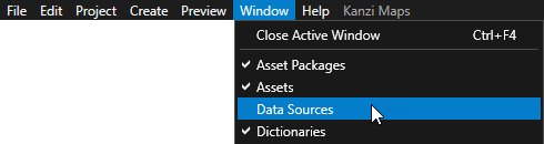
Tip
To view the Data Sources window, in the Kanzi Studio main menu, select Window > Data Sources.
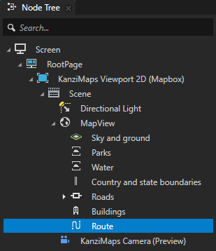
In the Node Tree in the MapView node, create a Route Renderer node and name it Route.
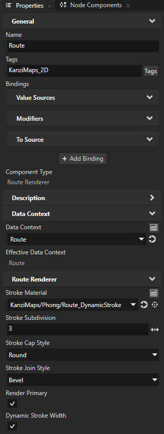
In the Properties, add and set:
Tags to KanziMaps_2D
This way you let the KanziMaps_Default render pass prefab know that the route is 2D-like content.
Kanzi Maps renders the route using KanziMaps_Default render pass prefab, because the KanziMaps Viewport 2D (Mapbox) node is set to use that render pass prefab.
Data Context > Data Context to Route
Tip
To set the Data Context property, you can drag a data source from the Data Sources window to the Effective Data Context property in the Properties.
Stroke Material to KanziMaps/Phong/Route_DynamicStroke
The Route Renderer node uses stroke to render the route, so the Stroke Material must support stroke. The KanziMaps/Phong/Route_DynamicStroke material uses the KanziMaps/FragmentPhong_DynamicStroke material type, which enables support for dynamic stroke.
Dynamic Stroke Width to enabled
This way you enable Kanzi Maps to vary the width of the route in the shader.
You cannot yet see the route in the Preview because there is no active route.
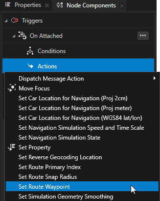
In the Node Tree, select the Screen node. In the Node Components, in the On Attached trigger, create a Set Route Waypoint action.
A Set Route Waypoint action sets the start or end point of the current route. An application can have only one current route and all Map View nodes share the same route. For this reason, it makes sense to create the Set Route Waypoint action in the Screen node. This way, Kanzi executes the actions once when it loads the application.
You use this action to set the start point of the route.
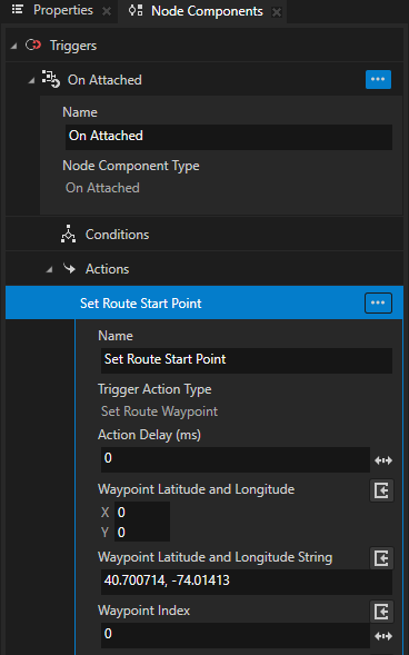
In the Set Route Waypoint action, set:
Name to Set Route Start Point
Waypoint Latitude and Longitude String to 40.700714, -74.01413
This way you set the latitude-longitude coordinates of the waypoint.
You can set the waypoint coordinates either with the Waypoint Latitude and Longitude or the Waypoint Latitude and Longitude String property. Do not set both properties.
Make sure that you leave the Waypoint Index set to 0. The value 0 corresponds to the start point of the route, and the value 1 corresponds to the end point of the route.
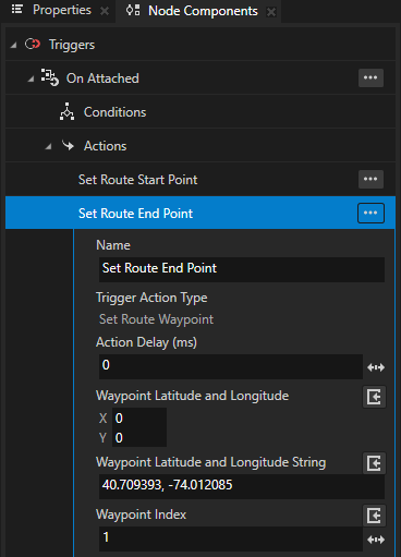
In the On Attached trigger, create another Set Route Waypoint action, and set:
Name to Set Route End Point
Waypoint Latitude and Longitude String to 40.709393, -74.012085
Waypoint Index to 1
You use this action to set the end point of the route.
Create a navigation marker
In this section, you create a visual marker that tracks the current navigation. You can use the Coordinate Renderer or Prefab Object Renderer node to implement a navigation marker. In this tutorial, you use the Coordinate Renderer.
Kanzi Maps Palette enables you to create a navigation marker with a few clicks. In this section, you learn how to create a navigation marker manually from scratch.
To create a navigation marker:
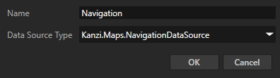
In the Data Sources, create a data source and set:
Name to Navigation
Data Source Type to Kanzi.Maps.NavigationDataSource
The Navigation Data Source provides information about the navigation state, such as turn-by-turn instructions.
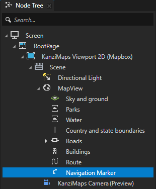
In the Node Tree in the MapView node, create a Coordinate Renderer node and name it Navigation Marker.
The Coordinate Renderer node allows you to set the coordinates at which you want to position the child node of the Coordinate Renderer.
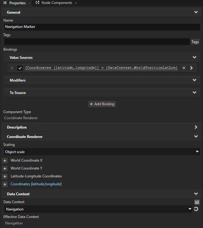
In the Properties:
Set Scaling to Object scale.
This way, you keep the size of the navigation marker the same when the zoom level of the map changes.
Add the Data Context > Data Context property and set it to the Navigation data source.
From the Data Sources, drag the Navigation > WorldPositionLatLon data object to the Properties and drop it on the Coordinates [latitude,longitude] property.
This way, you set the Navigation Marker node to move its child node to the current navigation position.
The Coordinate Renderer has multiple properties for specifying coordinates. The Coordinates [latitude,longitude] property is the most accurate one.
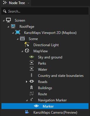
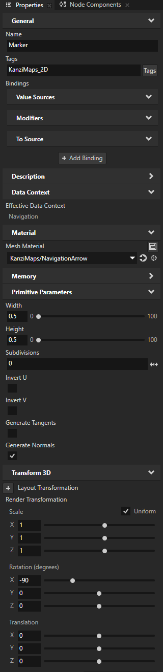
In the Navigation Marker node, create a Plane node and name it Marker. In the Properties, add and set:
Tags to KanziMaps_2D
Width and Height to 0.5
Mesh Material to KanziMaps/NavigationArrow
This is a textured material that renders a flat arrow that points to the direction of travel.
Render Transformation property Rotation X property field to -90
This way, you rotate the node along the xz plane of the map.
Make sure you set the Render Transformation property, not Layout Transformation. The Coordinate Renderer node updates its translation to the render transformation.
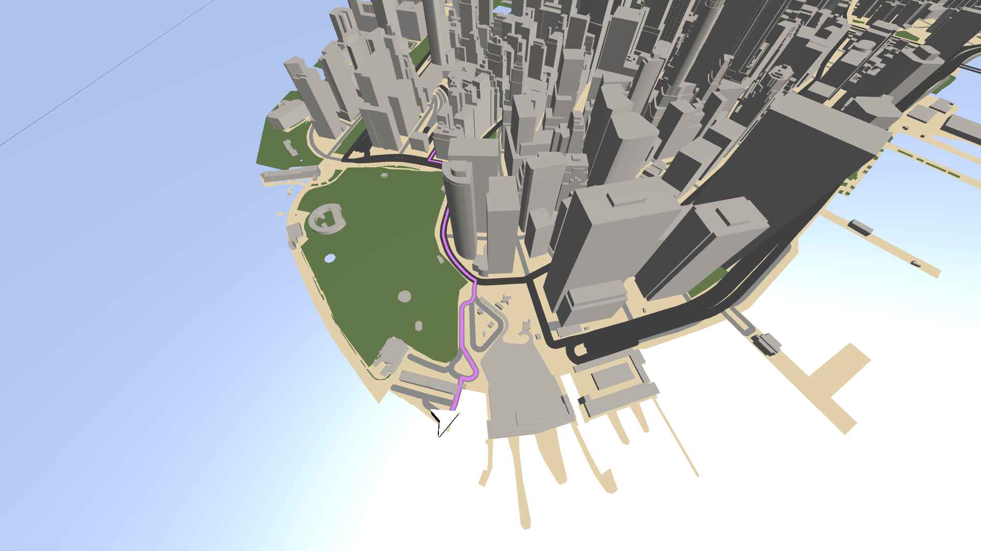
In the Preview, you can now see the navigation marker. If the navigation marker is not positioned at the start of the route, either pan the map or restart the Preview. The Coordinate Renderer updates the transformation only when the map or input coordinates move.

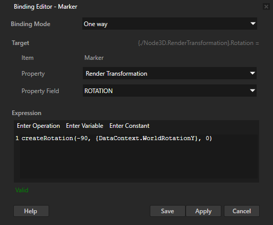
In the Properties, click + Add Binding and in the Binding Editor, set:
Property to Render Transformation
Property Field to ROTATION
Expression to
createRotation(-90, {DataContext.WorldRotationY}, 0)
You bind the Render Transformation Rotation property fields to these values:
X: -90
Y: the value of the WorldRotationY data object
Z: 0
This way, you orient the navigation marker to the direction of the route.
Simulate navigation
To simulate navigation:
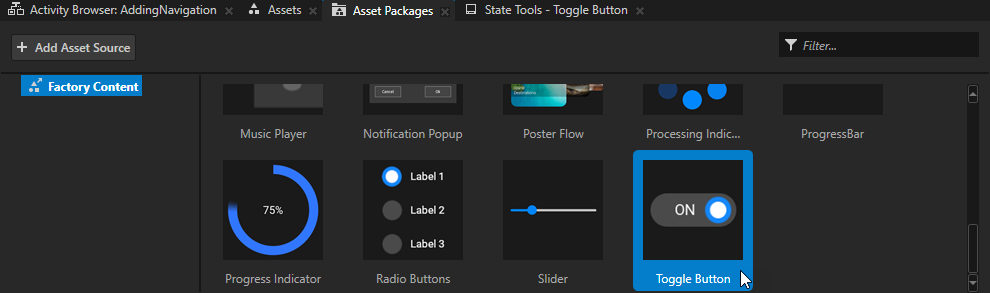
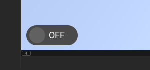
From the Asset Packages > Factory Content, drag the Toggle Button to the Preview.
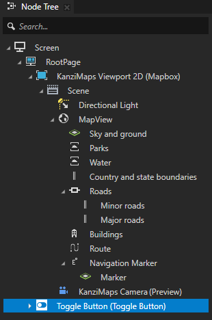
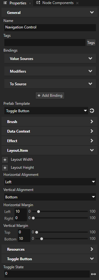
In the Node Tree, select the Toggle Button node. In the Properties, add and set:
Name to Navigation Control
Horizontal Alignment to Left
Vertical Alignment to Bottom
Horizontal Margin Left to 10
Vertical Margin Bottom to 10
Toggle State to 0
You set the toggle button to be in the toggled off state when the application starts.
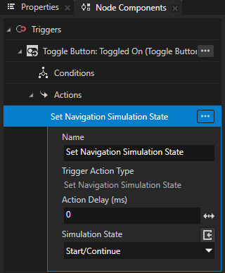
In the Node Components, create a Toggle Button: Toggled On message trigger.
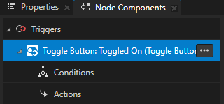
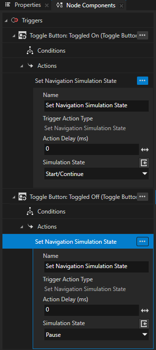
In the Toggle Button: Toggled On trigger, create a Set Navigation Simulation State action and set Simulation State to Start/Continue.
This way you set the navigation simulation to start when the Navigation Control toggle button is toggled on.
Create a Toggle Button: Toggled Off message trigger with a Set Navigation Simulation State action, and set Simulation State to Pause.
This way you set the navigation simulation to pause when the Navigation Control toggle button is toggled off.
What’s next?
In this tutorial you learned how to add basic routing and navigation simulation to a map. You can use the Button from Factory Content to create a reset button. In the Button: Click trigger create these actions:
Set Navigation Simulation State action that sets Simulation State to Pause.
Set Property action that sets in the Navigation Control node the Toggle State property to 0.
When you click the Button, the simulation resets to the beginning and stops.
See also
To learn more about the Palette, see Using the Palette.
To learn more about using the Route Renderer node, see Using the Route Renderer node.
To learn more about using the Coordinate Renderer node, see Using the Coordinate Renderer node.
To learn more about using the Prefab Object Renderer node, see Using the Prefab Object Renderer node.