Using the Stroke Mesh Renderer node
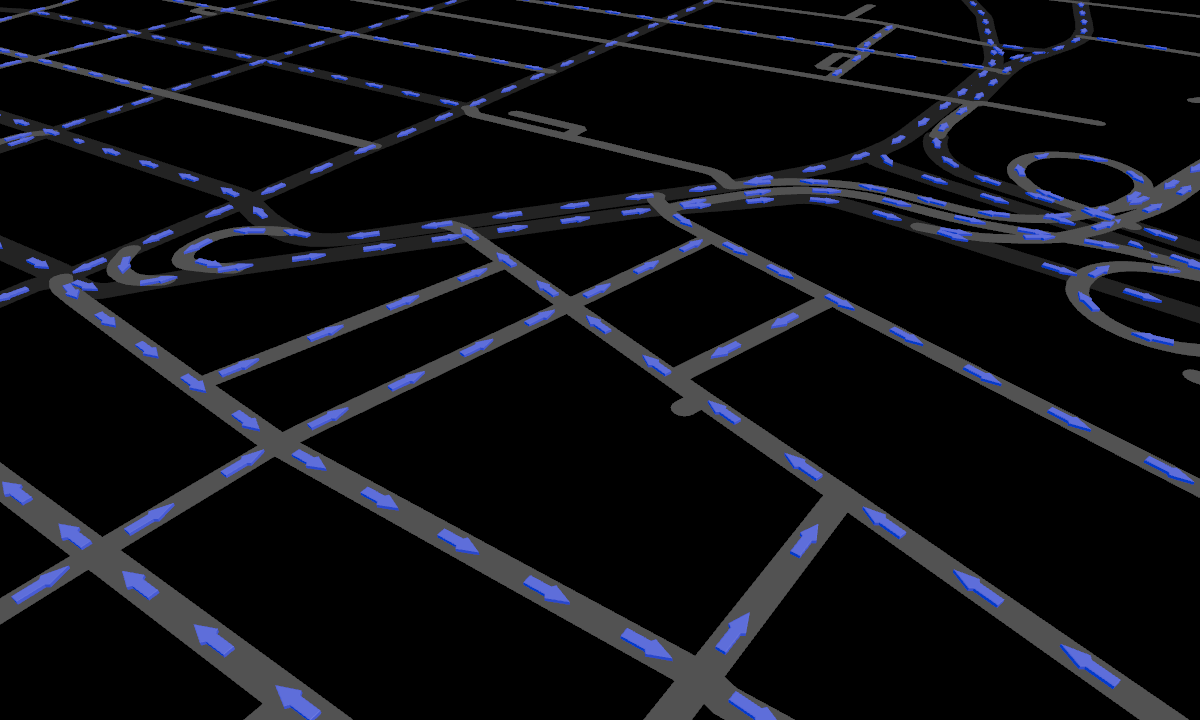
Use the Stroke Mesh Renderer node to render multiple copies of a mesh along a 2D or 3D line string. For example, you can render 3D elements along roads.
The Stroke Mesh Renderer supports only position, normal, and tangent mesh attributes. The Stroke Mesh Renderer does not support vertex color, skinning, or morphing.
In the image below:
Black line represents the line string geometry.
Blue box is the mesh.
Green circle is the location of the relative origin.
Orange circles are the anchor points.
When the Stroke Mesh Renderer instantiates copies of the mesh along the line string, it places the start and end anchor points on the line string geometry.
Dashed orange arrows show the direction in which the offset moves the anchors. Positive offset moves the anchors inwards.
The Stroke Mesh Renderer instantiates multiple meshes back-to-back, such that their end and start anchors overlap.
Creating a Stroke Mesh Renderer
To create a Stroke Mesh Renderer:
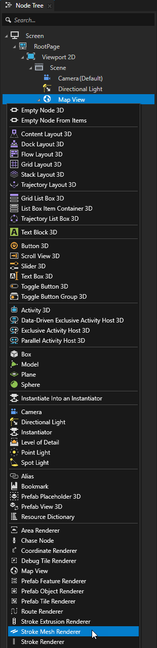
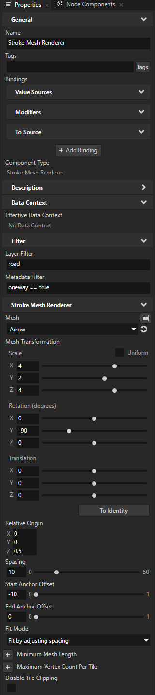
In the Node Tree, press Alt and right-click the Map View node where you want to instantiate copies of a mesh and select Stroke Mesh Renderer.
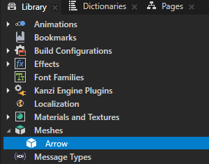
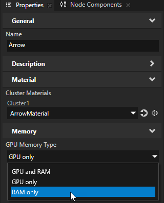
In the Library > Meshes, select the mesh that you want the Stroke Mesh Renderer to instantiate. In the Properties, set the GPU Memory Type to either GPU and RAM or RAM Only.
The Stroke Mesh Renderer requires the mesh resource to be available in RAM.
In the Node Tree, select the Stroke Mesh Renderer node. In the Properties, set:
Layer Filter to the name of the layer that provides the 2D or 3D line string map content on which you want to instantiate copies of a mesh.
For example, if you use Mapbox and want to instantiate the mesh along roads, set Stroke Layer Filter to road.
Stroke Metadata Filter to the metadata filter expression required to pick only specific type of content from the layer.
For example, if you use Mapbox and want to instantiate the mesh along the roads with one-way traffic, set it to
oneway == true
Tip
You can use the Renderer Editor to set layer and metadata filters. See Using the Renderer Editor.
Mesh to the mesh that you want to instantiate.
Mesh Transformation to the transformation that you want to use to orient, scale, and translate the mesh.
The Stroke Mesh Renderer applies this transformation to the vertices of the mesh before instantiating the mesh and before applying the value of the Relative Origin property.
Relative Origin to align the bounds of the mesh.
The Stroke Mesh Renderer sets the origin after it applies the value of the Mesh Transformation property.
The values 0 and 1 correspond to the bounds of the bounding box of the mesh. By default, the origin aligns to the front and bottom, and centers the mesh horizontally.
For example, to align:
To the front, bottom, and left corner, set the property fields to 0.
To the center of the mesh, set the property fields to 0.5.
To the back, top, and right corner, set the property fields to 1.
To disable the relative origin and set the origin at absolute (0, 0, 0), remove the Relative Origin property.
Spacing to the amount of space that you want between the instantiated meshes.
Start Anchor Offset to the offset along the x axis for the start anchor of the mesh, relative to the origin.
To move the anchor toward the center of the mesh, use a positive value. The default value is 0. This correspond to the origin of the mesh along the x axis.
End Anchor Offset to the offset along the x axis for the end anchor of the mesh, relative to the origin.
To move the anchor toward the center of the mesh, use a positive value. The default value is 0. This correspond to the sum of the origin of the mesh along the x axis and the length of the mesh.
Fit Mode to how you want to handle meshes that fit only partially on the line string:
Drop partial drops the last mesh if it does not completely fit on the line string.
Allow overflow allows the last mesh to overflow beyond the end of the line string.
Fit by adjusting spacing adjusts the spacing between the instantiated meshes to align the last mesh to the end of the line string.
Fit by adjusting x scale adjusts the scale of the instantiated meshes along the x axis to align the last mesh to the end of the line string.
Minimum Mesh Length to the minimum length for a mesh measured from the start anchor point to the end anchor point.
If the length of the mesh is less than the value of this property, Kanzi Maps can increase the spacing between the instantiated meshes to accommodate the length.
Setting the Fit Mode property to Fit by adjusting x scale also limits the length of the mesh to this value.
Maximum Vertex Count Per Tile to the maximum number of vertices that you want to create for a map tile.
When the number of vertices in the meshes to render exceeds this value, the Stroke Mesh Renderer drops the remaining mesh instances. The Stroke Mesh Renderer renders only those mesh instances whose vertices fit fully within this number.
Disable Tile Clipping to disabled if you want the Stroke Mesh Renderer to clip the geometry to the boundaries of map tiles. By default, the clipping is disabled.
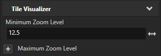
Controlling the visibility of content based on zoom level
To avoid visual clutter in your map, you can show content only at a specific range of zoom levels. Use the Minimum Zoom Level and Maximum Zoom Level properties to set the range of zoom levels at which a tile-based Renderer renders its content.
For example, in the Node Tree, select a Renderer node. In the Properties, add and set the Minimum Zoom Level property to 12.5.
This way, you hide the content rendered by the Renderer when in the Map View node the value of the Zoom Level property is less than 12.5.