Using the Route Renderer node
Use the Route Renderer node to render routes for navigation.
The Route Renderer renders 2D line strings and can get its input geometry from:
The Route Data Source. See Using the Route Data Source.
GeoJSON or polyline that you set in the Route Geometry property. See Using GeoJSON or a polyline as the route geometry.
The Route Renderer works similarly to the Stroke Renderer, but the Route Renderer renders non-tiled line string geometry, which is why you do not use layer and metadata filters to select the input geometry. You can configure the geometry rendered by a Route Renderer the same way as the Stroke Renderer. See Using the Stroke Renderer node.
The Route Renderer uses some of the functionality of the Stroke Extrusion Renderer to render extruded 3D routes. See Using the Stroke Extrusion Renderer node.
Learn how to use the Route Renderer node by completing a tutorial. See Tutorial: Navigation.
Creating a Route Renderer using the Palette
This section explains how to use the Kanzi Maps Palette to quickly create and set up a Route Renderer. To learn how to create and set up a Route Renderer manually, see Creating a Route Renderer manually.
To create a Route Renderer using the Palette:
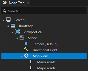
In the Node Tree, select the Map View node where you want to render a route.
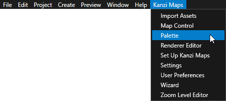
In the Kanzi Studio main menu, select Kanzi Maps > Palette.
When Kanzi Studio asks whether you want to import assets, click Yes.
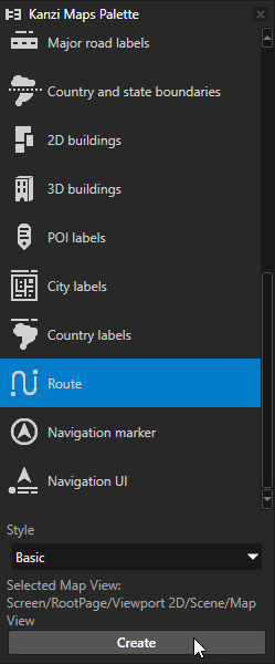
In the Kanzi Maps Palette, select Route and click Create.
In the Confirm modifications dialog, click Apply Modifications to let Kanzi Studio modify your project as needed to render the content that you selected.
Kanzi Studio creates:
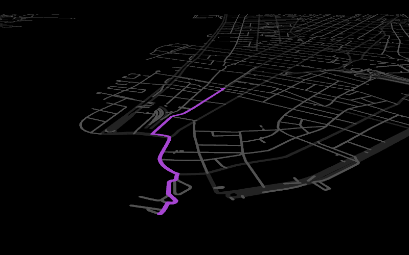
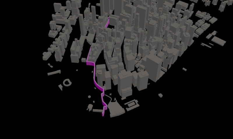
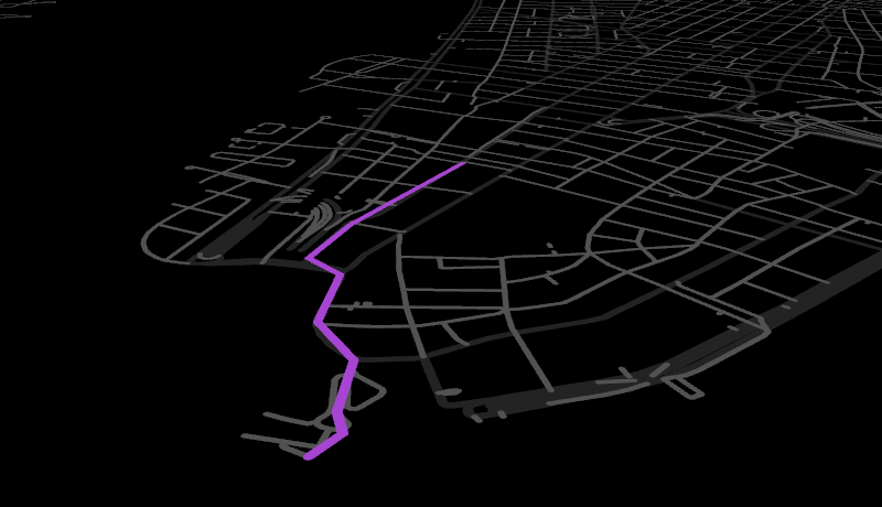
In the Screen > Node Components, an On Attached trigger that contains the Set Route Waypoints actions that set the start and end of an example route in Downtown Manhattan.
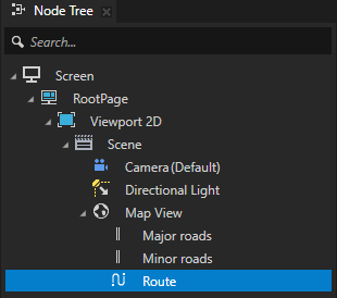
In the Map View node, a Route Renderer node that renders the example route using:
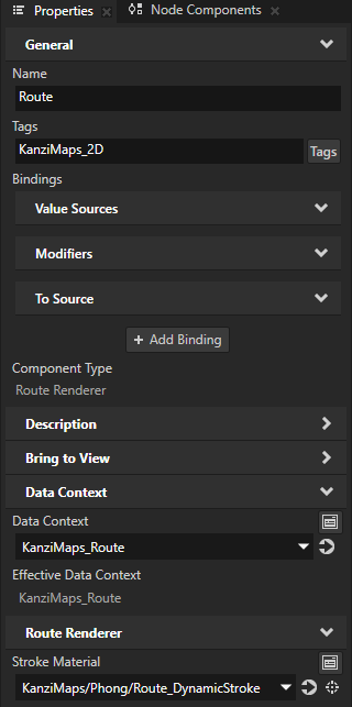
The KanziMaps_Route Route Data Source to provide the route data. See Using the Route Data Source.
The KanziMaps > Phong > Route_DynamicStroke material to set the appearance of the route.
Creating a Route Renderer manually
This section explains how you can create and set up a Route Renderer manually. To learn how to use the Kanzi Maps Palette to quickly render a route, see Creating a Route Renderer using the Palette.
To create a Route Renderer manually:
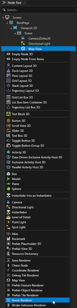
In the Node Tree, press Alt and right-click the Map View node where you want to render a route and select Route Renderer.
Create the route:
In the Node Tree, select the Screen node. In the Node Components > Triggers, create an On Attached trigger.
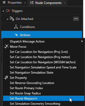
In the On Attached trigger, create a Set Route Waypoint action.
A Set Route Waypoint action sets the start or end point of the current route. An application can have only one current route and all Map View nodes share the same route. For this reason, it makes sense to create the Set Route Waypoint action in the Screen node. This way, Kanzi executes the actions once when it loads the application.
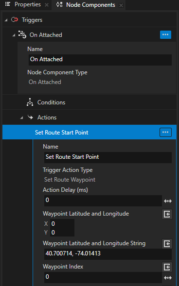
You use this action to set the start point of the route.
In the Set Route Waypoint action, set the latitude-longitude coordinates of the start point of the route.
For example, set the Waypoint Latitude and Longitude String to 40.700714, -74.01413.
Tip
You can set the waypoint coordinates either in the Waypoint Latitude and Longitude or the Waypoint Latitude and Longitude String property. Do not set both properties.
Make sure that you leave the Waypoint Index set to 0. The value 0 corresponds to the start point of the route, and the value 1 corresponds to the end point of the route.
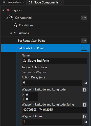
In the On Attached trigger, create another Set Route Waypoint action, where you set:
The latitude-longitude coordinates of the end point of the route.
For example, set Waypoint Latitude and Longitude String to 40.709393, -74.012085.
Waypoint Index to 1.
Provide the route data for the Route Renderer:
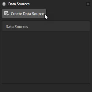
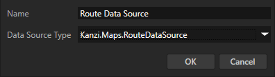
In the Data Sources window, click Create Data Source and set the Data Source Type to Kanzi.Maps.RouteDataSource.
The Route Data Source provides data about routes.
See Using the Route Data Source.
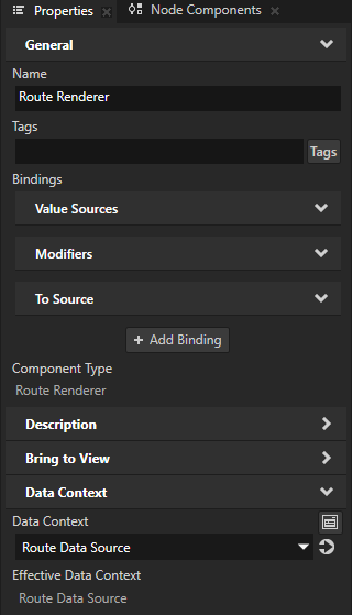
In the Node Tree, select the Route Renderer node. In the Properties, add and set the Data Context > Data Context property to the Route Data Source that you created.
Tip
Instead of using a data source, you can set the Route Renderer node to get its input geometry from GeoJSON or a polyline. See Using GeoJSON or a polyline as the route geometry.
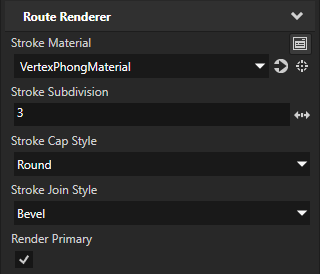
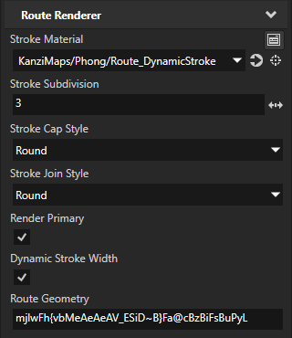
In the Properties, set the Stroke Material property to the material that you want to use to render the route.
Keep in mind that if you want to change the width of the route stroke dynamically, you need to use a material that supports dynamic stroke width. For example, you can use the KanziMaps/Phong/Route_DynamicStroke material that comes with the Kanzi Maps Assets. To import the assets, in the Kanzi Maps main menu, select Import Assets.
When you do not need dynamic stroke width, you can use any standard material.
For example, set the Stroke Material to the VertexPhongMaterial material. Use the material properties to set the color of the route.
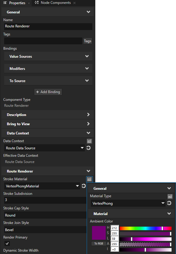
In the Properties, you can use:
Stroke Subdivision to set a limit for round caps and joins. See Setting the shape of the stroke.
The number of extra vertices that Kanzi Maps generates is in the order of \(2^{subdivisions}\).
Stroke Cap Style to set the shape of the route stroke at the ends of a path. See Setting the shape of the stroke at the ends of a path.
Stroke Join Style to set the shape of the route stroke at corners. See Setting the shape of the stroke at corners.
Render Primary to set whether to render the primary route.
When you disable this property, if the Route Data Source provides a secondary route, the Route Renderer node renders that route.
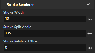
Stroke Width to set the width of the route stroke.
Stroke Split Angle to set the turn angle in degrees after which you want to split the stroke to two strokes that have their own caps.
Stroke Relative Offset to set the offset of the stroke relative to the width.
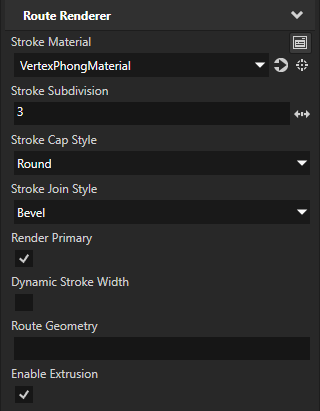
In the Properties, you can enable either the Dynamic Stroke Width or the Enable Extrusion:
Dynamic Stroke Width sets whether to enable changing the width of the route stroke dynamically.
This requires a custom shader. For example, the KanziMaps > Phong > Route_DynamicStroke material supports dynamic stroke width.
Enable Extrusion sets whether to enable extrusion for the route rendering.
Do not enable both of these properties.
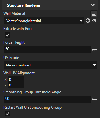
(Optional) If you enabled extrusion, use the Structure Renderer properties to set how you want to render the extrusion.
For example, set:
Wall Material to the same material that you set in the Stroke Material property
Force Height to 50
This way, you set the height of the extrusion in projected meters.
Setting the shape of the stroke
The Route Renderer node by default renders strokes that have round ends and bevelled corners. You can use the Stroke Cap Style and Stroke Join Style properties to set the shape of the stroke.
Setting the shape of the stroke at the ends of a path
To set the shape of a stroke at the ends of a path, use the Stroke Cap Style property.
In the Properties, set the Stroke Cap Style to:
Round to extend the stroke by a half circle whose diameter is equal to the stroke width. This is the default value. |

|
Square to extend the stroke by a square whose width is half of the stroke width. |

|
Butt to not extend the stroke beyond its endpoint. |

|
Setting the shape of the stroke at corners
To set the shape of the corner that is formed when the ends of two strokes meet or overlap, use the Stroke Join Style property.
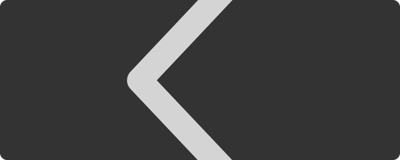
Bevel to use a bevelled corner. This is the default value. To optimize the amount of geometry that Kanzi Maps generates, use this style whenever it is visually acceptable. |
|
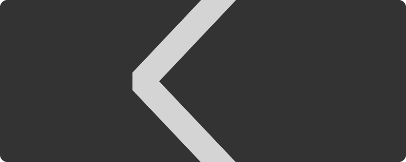
Round to use a round corner. |
|
Using GeoJSON or a polyline as the route geometry
In the Route Renderer, you can use the Route Geometry property to provide the route geometry as a GeoJSON line string feature or a base64-encoded polyline.
Use the Route Geometry property when the geometry comes from an external source, such as Kanzi Connect.
GeoJSON example:
{
   “type”: “LineString”,
   “coordinates”: [[lon, lat], [lon, lat]]
}
Polyline example:
mjlwFh{vbMeAeAeAV_ESiD~B}Fa@cBzBiFsBuPyL
Tip
You can use the Google Maps Interactive Polyline Encoder Utility to encode lists of locations into polylines.
Controlling the visibility of content based on zoom level
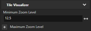
To avoid visual clutter in your map, you can show content only at a specific range of zoom levels. Use the Minimum Zoom Level and Maximum Zoom Level properties to set the range of zoom levels at which a tile-based Renderer renders its content.
For example, in the Node Tree, select a Renderer node. In the Properties, add and set the Minimum Zoom Level property to 12.5.
This way, you hide the content rendered by the Renderer when in the Map View node the value of the Zoom Level property is less than 12.5.
See also
Using the Stroke Renderer node
Using the Stroke Extrusion Renderer node