Using the Stroke Renderer node
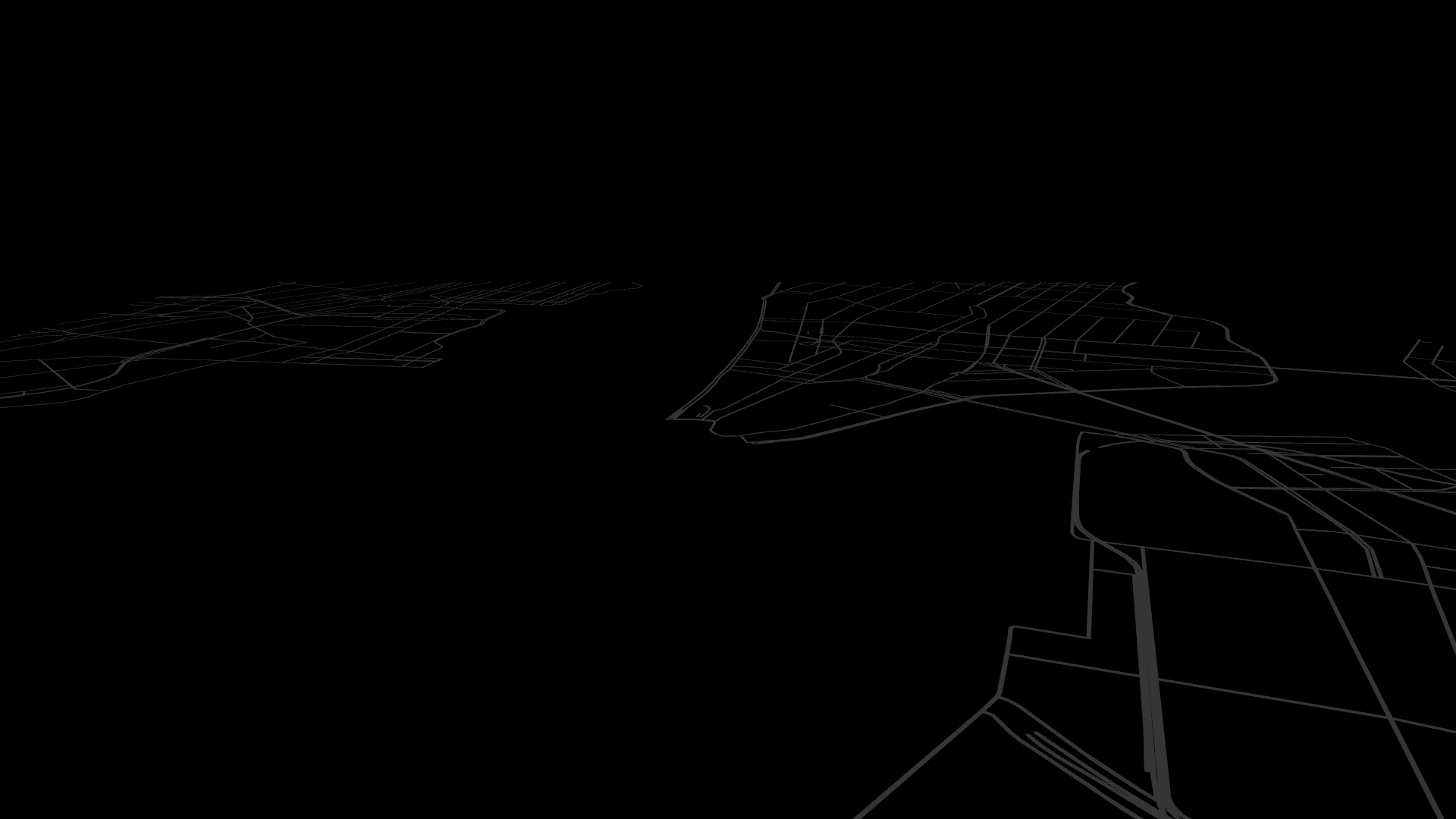
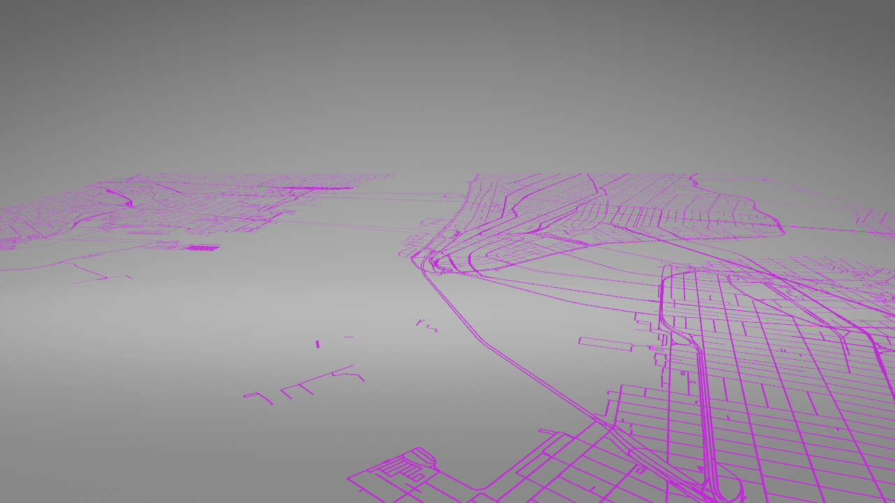
Use the Stroke Renderer node to render roads, rivers, and borders. The Stroke Renderer renders stroked 2D and 3D line string geometry and stroked 2D polygons.
Learn how to use the Stroke Renderer node by completing a tutorial. See Tutorial: Filter map content.
Creating a Stroke Renderer using the Palette
This section explains how to use the Kanzi Maps Palette to quickly create and set up a Stroke Renderer that renders roads or borders. To learn how to create and set up a Stroke Renderer manually, see Creating a Stroke Renderer manually.
To create a Stroke Renderer using the Palette:
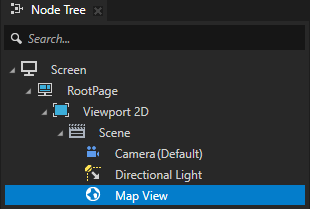
In the Node Tree, select the Map View node where you want to render roads or borders.
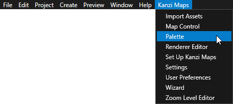
In the Kanzi Studio main menu, select Kanzi Maps > Palette.
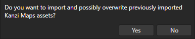
When Kanzi Studio asks whether you want to import assets, click Yes.
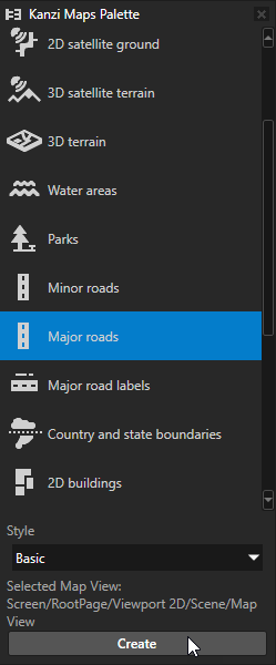
In the Kanzi Maps Palette:
Select the type of content that you want to render:
Minor roads
Major roads
Country and state boundaries
For example, select Major roads
(Optional) To render the content with a textured material, set Style to Textured.
Click Create
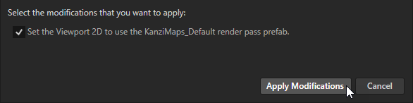
In the Confirm modifications dialog, click Apply Modifications to let Kanzi Studio modify your project as needed to render the content that you selected.
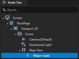
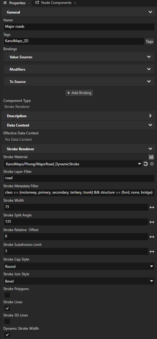
Kanzi Studio creates in the Map View node a Stroke Renderer node and sets:
Stroke Material to the material that defines the appearance of the geometry rendered by that node.
Stroke Layer Filter to the name of the layer that provides the geometry to render.
For example, if you use Mapbox and create Major roads, Kanzi Studio sets the Stroke Layer Filter to road, which contains the geometry for features such as roads, railways, paths, and their labels. See Supported backends.
Stroke Metadata Filter to the metadata filter expression required to render only specific type of content from the layer.
For example, if you use Mapbox and create Major roads, Kanzi Studio sets the Stroke Metadata Filter to
class == {motorway, primary, secondary, tertiary, trunk} && structure == {ford, none, bridge}This picks from the
roadlayer the classes that render highways and other important roads, and all structures but tunnels.Stroke Width to the width of the stroke in target projection meters.
Dynamic Stroke Width to enabled.
This enables Kanzi Maps to vary the width of the stroke in the shader. The Stroke Material must support dynamic stroke width.
Creating a Stroke Renderer manually
This section explains how you can create and set up a Stroke Renderer manually. To learn how to use the Kanzi Maps Palette to quickly render roads or borders, see Creating a Stroke Renderer using the Palette.
Creating a Stroke Renderer
In this example, you create a Stroke Renderer node that renders all roads expect for ferry lines, paths, and pedestrian roads. When you build a map, create multiple Stroke Renderer nodes, each of which you set to render different types of roads. That way, you can render different types of roads with different stroke widths and materials.
To create a Stroke Renderer manually:
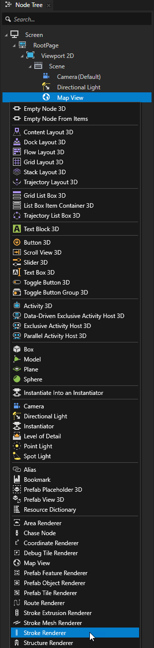
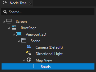
In the Node Tree, press Alt and right-click the Map View node where you want to render roads and select Stroke Renderer.
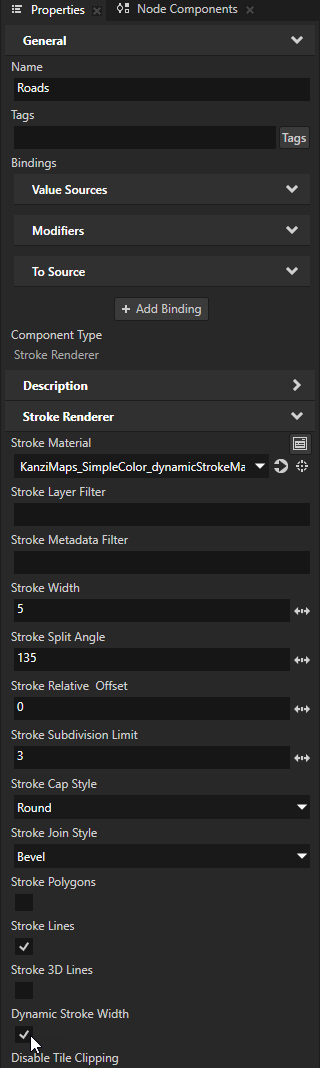
For example, create a Stroke Renderer node that you use to render roads, and name it Roads.
In the Properties, set the Stroke Material property to the material that you want to use to set the appearance of the stroke.
If you want to adjust the width of the stroke dynamically, you must use a material that supports that. See Stroke-specific material types.
For example:
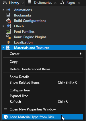
In the Library, right-click Materials and Textures and select Load Material Type from Disk.
Go to
<KanziWorkspace>/Engine/plugins/maps/assets/MaterialTypesand load theKanziMaps_SimpleColor_dynamicStroke.kzmatmaterial type file.In the Properties, set the Stroke Material to the KanziMaps_SimpleColor_dynamicStrokeMaterial material.
This material supports dynamic stroke width.
(Optional) If you set the Stroke Material property to a material that supports dynamic stroke width, in the Properties, enable the Dynamic Stroke Width property.
This way you enable Kanzi Maps to vary the width of the route in the shader if the Stroke Material supports that.
In the Properties, set:
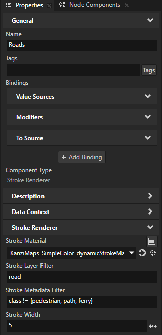
Stroke Layer Filter to the name of the layer that provides the type of content that you want to show.
For example, if you use Mapbox and want to show roads, set Stroke Layer Filter to road. The
roadlayer contains lines, points, and polygons for features such as roads, railways, paths and their labels. See Supported backends.(Optional) Stroke Metadata Filter to the metadata filter expression required to render only specific type of content from the layer.
For example, if you use Mapbox and want to render all roads expect for ferry lines, paths, and pedestrian roads, set it to
class != {pedestrian, path, ferry}
Tip
You can use the Renderer Editor to set layer and metadata filters. See Using the Renderer Editor.
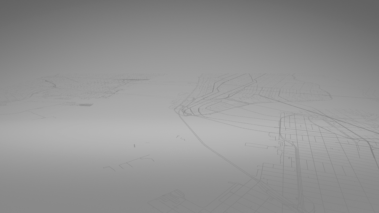
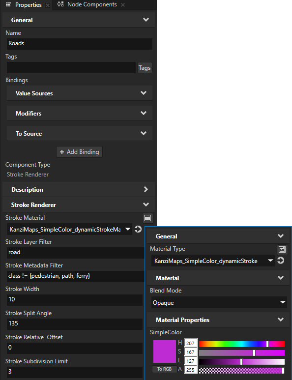
Adjust the appearance of the rendering.
For example, adjust the value of the Stroke Width property and the color of the material that you use to render the stroke.
Creating a Stroke Renderer that renders stroke with a textured material
To create a Stroke Renderer that renders stroke with a textured material:
In the Node Tree, press Alt and right-click the Map View node where you want to render roads and select Stroke Renderer.
For example, create a Stroke Renderer node that you use to render roads, and name it Roads.
In the Properties, set the Stroke Material to the material that you want to use to set the appearance of the stroke.
You must use a material that supports UV coordinates. See Stroke-specific material types.
For example:
In the Library, right-click Materials and Textures and select Load Material Type from Disk.
Go to
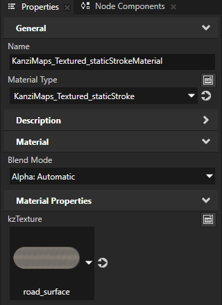
<KanziWorkspace>/Engine/plugins/maps/assets/MaterialTypesand load theKanziMaps_Textured_staticStroke.kzmatmaterial type file.In the Properties, set the Stroke Material to the KanziMaps_Textured_staticStrokeMaterial material.
In the Properties, set:
Stroke Layer Filter to the name of the layer that provides the type of content that you want to show.
For example, if you use Mapbox and want to show roads, set Stroke Layer Filter to road. The
roadlayer contains lines, points, and polygons for features such as roads, railways, paths and their labels. See Supported backends.(Optional) Stroke Metadata Filter to the metadata filter expression required to render only specific type of content from the layer.
For example, if you use Mapbox and want to render all roads expect for ferry lines, paths, and pedestrian roads, set it to
class != {pedestrian, path, ferry}Tip
You can use the Renderer Editor to set layer and metadata filters. See Using the Renderer Editor.
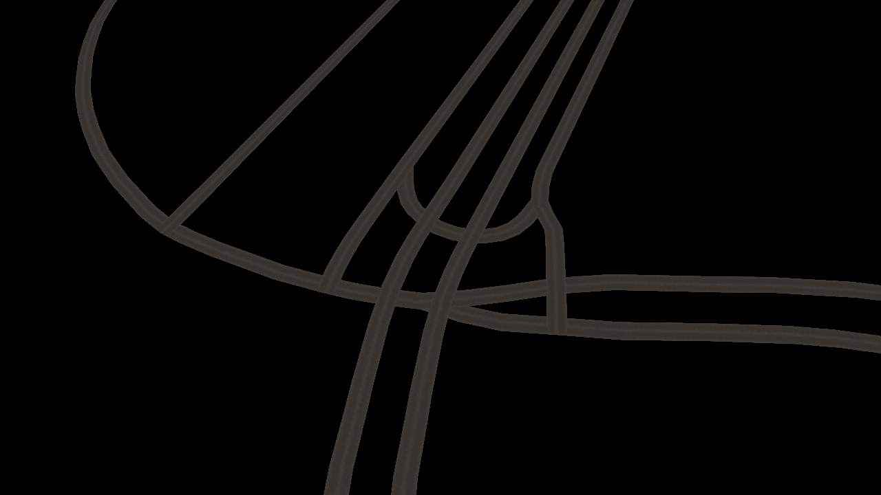
In the Properties, click
 next to the Stroke Material property to go to the material, and set:
Blend Mode to Alpha: Automatic
kzTexture to the texture that you want to render on the stroke
Use a render pass prefab that disables depth write for the Stroke Renderer node.
For example:
In the Kanzi Maps main menu, select Import Assets. See Using the Kanzi Maps assets.
In the Node Tree, select the Stroke Renderer node. In the Properties, set the Tags property to KanziMaps_2D.
In the Node Tree, select the Viewport 2D node. In the Properties, set the Render Pass Prefab property to the KanziMaps_Default render pass prefab.
Stroke-specific material types
The default stroke configuration works with most standard materials. To change the width of the stroke dynamically, you need a custom vertex shader. To use UV coordinates, you need custom vertex and fragment shaders.
In the <KanziWorkspace>/Engine/plugins/maps/assets/MaterialTypes directory, you can find these material type files:
File |
Description |
|---|---|
|
Supports dynamic stroke. |
|
Supports UV coordinates. |
|
Supports both dynamic stroke and UV coordinates. |
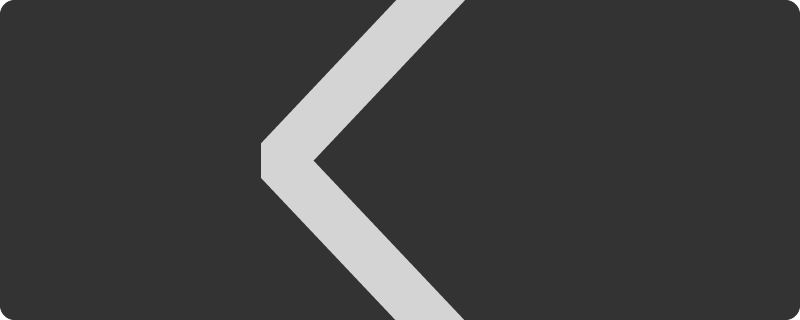
The textured stroke material types assume that the stroke texture contains start and end caps. Orient the stroke texture horizontally, and include the caps in the texture so that the length of each cap is half of the height of the texture:
The material type repeats the body of the texture. For example, if the body part of the texture is twice the height of the texture and the width of the stroke is five projected meters, the length of the body is ten meters and the body repeats every ten meters.
Setting the shape of the stroke
The Stroke Renderer node by default renders strokes that have round ends and bevelled corners. You can use the Stroke Cap Style and Stroke Join Style properties to set the shape of the stroke.
Setting the shape of the stroke at the ends of a path
To set the shape of a stroke at the ends of a path, use the Stroke Cap Style property.
In the Properties, set the Stroke Cap Style to:
Round to extend the stroke by a half circle whose diameter is equal to the stroke width. This is the default value. |

|
Square to extend the stroke by a square whose width is half of the stroke width. |

|
Butt to not extend the stroke beyond its endpoint. |

|
Setting the shape of the stroke at corners
To set the shape of the corner that is formed when the ends of two strokes meet or overlap, use the Stroke Join Style property.
Bevel to use a bevelled corner. This is the default value. To optimize the amount of geometry that Kanzi Maps generates, use this style whenever it is visually acceptable. |
|
Round to use a round corner. |

|
Vertex layouts
When you disable the Dynamic Stroke Width property, the Stroke Renderer node uses this vertex layout:
Vertex attribute |
Description |
|---|---|
|
Vertex position |
|
Constant Vector3(0, 1, 0) for 2D line strings, and an actual normal for 3D line strings. |
|
An attribute with the components U, V, and W, where:
|
|
Tangent that points along the direction of the line segment oriented from the start toward the end. |
When you enable the Dynamic Stroke Width property, the Stroke Renderer node uses this vertex layout:
Vertex attribute |
Description |
|---|---|
|
Line center position. |
|
An attribute with the components X, Y, and Z, where:
|
|
An attribute with the components U, V, and W, where:
|
|
An attribute with the components X, Y, and Z, where:
|
Texturing
These aspects complicate the texturing of stroke:
Handling of the caps and the body of the stroke
The U range is separated such that the 0 to 1 range is reserved for the body of the line stroke. This way the body can use a repeating texture. This image shows how U is assigned in vertices of dynamic and static stroke width. With static stroke width
kzTextureCoodinate0.zis negative when the vertex belongs to a cap.Interpolating the U coordinate at joins
This image shows the geometry of a bevel join.
The inner vertex indicated by a black dot is marked with U value of -2.0. That is, when
kzTextureCoordinate0.xequals -2.0, in the vertex shader it is known that this vertex is an inner vertex. To interpolate U such that it smoothly interpolatesU0toU1at all points of the join, except for the inner vertex:Use a three-component varying, where:
The first component is U.
The second component is V.
The third component is 0 for inner vertex, and 1 for all others.
In the vertex shader, premultiply U with the third component.
In the fragment shader, divide the interpolated U by the interpolated third component.
This creates a fan-like gradient for U centered at the inner vertex without the need to further split the geometry.
Handling the effect of dynamic stroke width to the U coordinate of individual vertices
This is relevant only for stroke that has dynamic width.
In the above image, the blue area is the join, and the grey areas are the body of the stroke.
U0is the start value for the join andU1is the end value for the join. The size of the join relative to the body changes when the stroke width changes through a uniform. For this reason, the exact values forU0andU1change when the stroke width varies. When the stroke width increases,U0decreases andU1increases. To handle this dynamic change of U, the required width-dependent offset is encoded inkzTextureCoordinate0.y.To apply the offset, U is moved bykzTextureCoordinate0.ymultiplied by the stroke width for body vertices.
Controlling the visibility of content based on zoom level
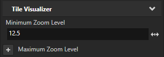
To avoid visual clutter in your map, you can show content only at a specific range of zoom levels. Use the Minimum Zoom Level and Maximum Zoom Level properties to set the range of zoom levels at which a tile-based Renderer renders its content.
For example, in the Node Tree, select a Renderer node. In the Properties, add and set the Minimum Zoom Level property to 12.5.
This way, you hide the content rendered by the Renderer when in the Map View node the value of the Zoom Level property is less than 12.5.
Clipping geometry to the boundaries of map tiles
The Disable Tile Clipping property sets whether the Stroke Renderer node clips geometry to the boundaries of map tiles. By default, the Stroke Renderer node clips the geometry.
If overlapping geometry on tile boundaries is not an issue with the material that you use, you can disable clipping by setting the Disable Tile Clipping property to enabled. This can reduce tile processing time.