Shader graphs (Experimental)
Note
The Shader Graph Editor is an experimental feature that may change or be removed in future versions of Kanzi Studio. To enable it, see Enabling the Shader Graph Editor.
The Shader Graph Editor is a visual node-based tool for building GLSL fragment shaders in Kanzi Studio. Instead of writing shader code by hand, you create a graph of connected nodes that define the shader logic. When you generate the shader, Kanzi Studio compiles the graph into a GLSL fragment shader and creates a Material Type from it. For physically-based graphs, Kanzi Studio also creates a Material that uses that Material Type.
Enabling the Shader Graph Editor
To enable the Shader Graph Editor:
In Kanzi Studio, select Edit > User Preferences.
Select the Experimental tab.
In the Web-based editors section, enable Shader graph editor.
Material types
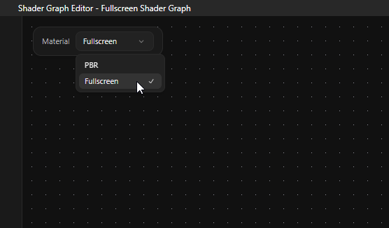
Each shader graph targets one material type. The material type sets which input ports the Material Output node exposes and what kind of GLSL fragment shader Kanzi Studio generates.
You set the material type from the Material dropdown in the top-left corner of the editor.
Material type |
Description |
|---|---|
PBR |
Physically-based material. The Material Output node exposes Base Color, Metallic, Roughness, Normal, Emissive, and AO (ambient occlusion) inputs. When you generate the shader, Kanzi Studio creates a Material Type and a Material that uses it. |
Fullscreen |
Fullscreen effect material. The Material Output node exposes a single Color input. Use this material type for postprocessing effects and similar fullscreen passes. |
When you switch material types, Kanzi Studio reconfigures the Material Output node and disconnects any inputs that no longer exist on the new port set.
Node types
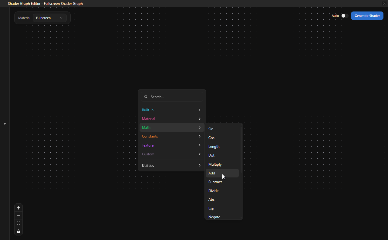
The Shader Graph Editor provides 45 nodes across 7 catalog categories. The Add Node menu groups them by category and includes a search field that filters every category at once. Math nodes are polymorphic. They adapt their input and output types to match the connected ports.
In addition to the catalog categories, you can add Note nodes from the Utilities submenu and create Group nodes from a selection.
Constants
Constant nodes hold literal values that you edit directly on the node.
Node |
Description |
Outputs |
|---|---|---|
Scalar |
Constant float value. |
result (float) |
Int |
Constant integer value. |
result (int) |
Vec2 |
Constant 2D vector. |
result (vec2), x (float), y (float) |
Vec3 |
Constant 3D vector. |
result (vec3), x (float), y (float), z (float) |
Vec4 |
Constant 4D vector. |
result (vec4), x (float), y (float), z (float), w (float) |
Color3 |
RGB color constant. Click the swatch on the node to open the color picker. |
result (vec3) |
Color4 |
RGBA color constant. Click the swatch on the node to open the color picker. |
result (vec4) |
You can promote any constant node to a parameter so that its value becomes a uniform that you can edit in the Kanzi Studio Properties panel. See Parameters.
Built-in
Built-in nodes provide values that the engine produces during rendering.
Node |
Description |
Inputs |
Outputs |
|---|---|---|---|
UV |
UV texture coordinates. |
— |
uv (vec2), u (float), v (float) |
Time |
Elapsed time and per-frame delta. |
— |
Seconds (float), Delta (float) |
TilingOffset |
Apply tiling and offset to UV coordinates. |
uv (vec2), tiling (vec2), offset (vec2) |
result (vec2) |
Combine4 |
Combine four floats into a vec4. |
r (float), g (float), b (float), a (float) |
result (vec4) |
RGB |
Combine three floats into a vec3. |
r (float), g (float), b (float) |
result (vec3) |
Math
Node |
Description |
|---|---|
Sin |
Sine function. |
Cos |
Cosine function. |
Abs |
Absolute value. |
Exp |
Natural exponentiation ( |
Negate |
Negation (unary minus). |
Normalize |
Vector normalization. |
Length |
Vector magnitude. Always outputs float. |
Dot |
Dot product. Always outputs float. |
Cross |
Cross product of two vec3 values. |
Distance |
Distance between two vec3 values. Always outputs float. |
Reflect |
Reflect an incident vec3 across a vec3 normal. |
Add |
Addition. |
Subtract |
Subtraction. |
Multiply |
Multiplication. |
Divide |
Division. |
Max |
Component-wise maximum. |
Min |
Component-wise minimum. |
Mix |
Linear interpolation ( |
Lerp |
Linear interpolation ( |
Power |
Exponentiation. |
Clamp |
Clamp value between a minimum and a maximum. |
Material
Material nodes provide per-fragment surface and view data that the engine populates from the rendered geometry. They have no inputs.
Node |
Description |
Outputs |
|---|---|---|
Normal |
Surface normal in world space. |
normal (vec3), x (float), y (float), z (float) |
Tangent |
Surface tangent in world space. |
tangent (vec3), x (float), y (float), z (float) |
Bitangent |
Computes the bitangent from a normal and a tangent. Connect any vec3 sources. You do not need to use the Normal and Tangent nodes. |
bitangent (vec3) |
WorldPos |
World-space position of the current fragment. |
pos (vec3), posX (float), posY (float), posZ (float) |
CameraPos |
World-space position of the active camera. |
pos (vec3), posX (float), posY (float), posZ (float) |
ViewDir |
Normalized view direction from the fragment to the camera, in world space. |
viewDir (vec3) |
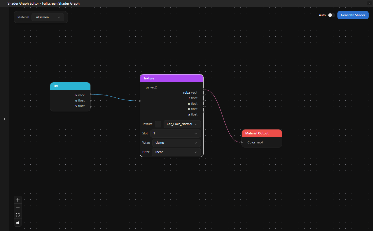
Texture
Texture nodes sample texture resources from the Kanzi Studio Library. The Texture resource picker lists every texture in the project.
Node |
Description |
|---|---|
Texture |
Sample a texture. Pick the Texture resource on the node, or leave it unset to use a placeholder. Properties: Wrap (repeat, clamp, mirror), Filter (linear, nearest). Inputs: uv (vec2). Outputs: rgba (vec4), r, g, b, a (float). |
NormalMap |
Sample a normal map and transform the result into world space. Inputs: uv (vec2), textureIndex (int), strength (float), worldNormal (vec3). Outputs: result (vec3). |
UnpackNormal |
Convert an already-sampled normal-map color into a world-space normal vector. Inputs: normalSample (vec4), strength (float), worldNormal (vec3). Outputs: result (vec3). |
Custom
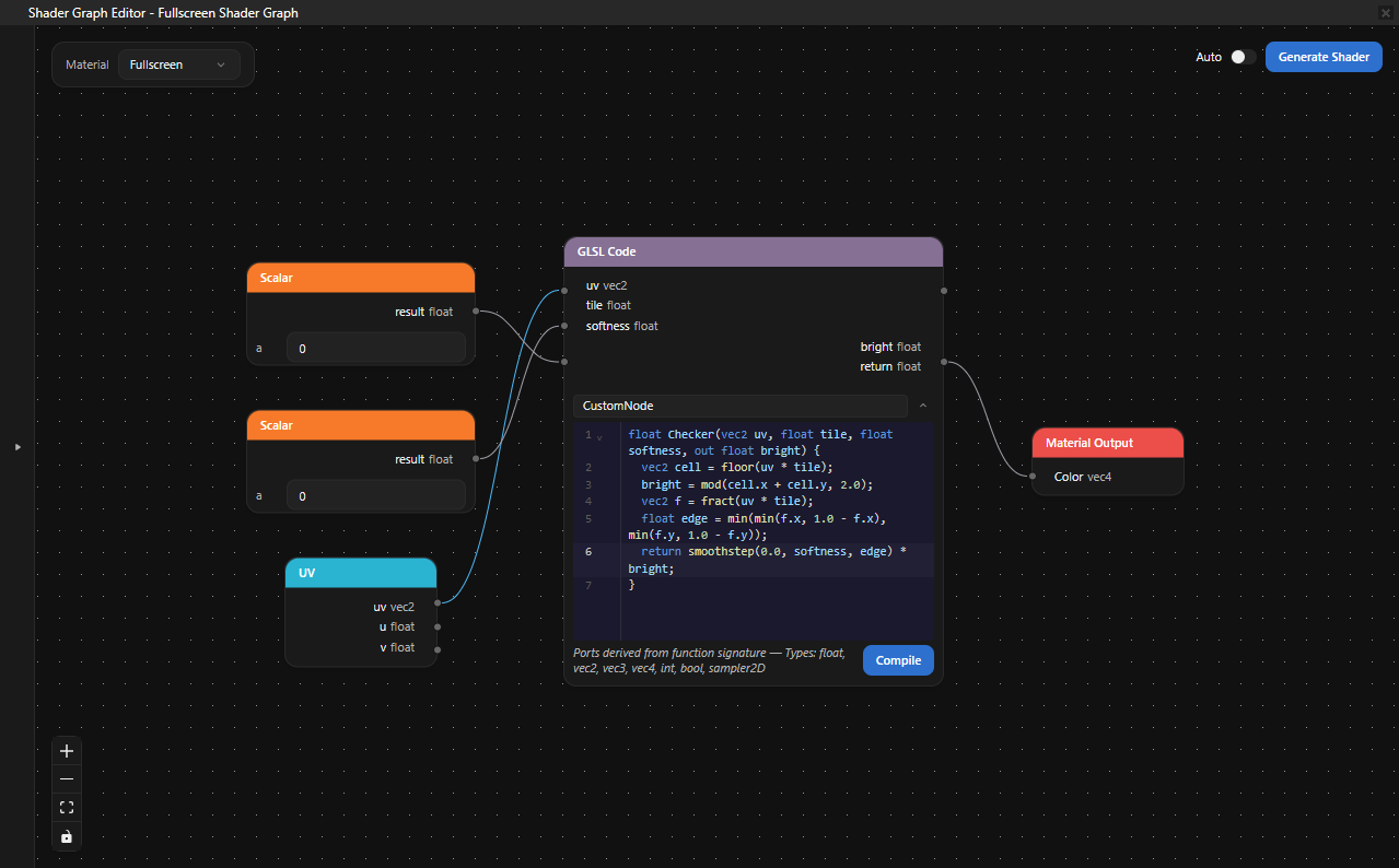
The Custom category lets you embed hand-written GLSL alongside the graph.
Node |
Description |
|---|---|
GLSL Code |
Author a small GLSL function inside the editor. Set Function name on the node and write the body in the embedded code editor. The node parses the function signature and generates ports from it: each |
For example, this GLSL Code node body produces three input ports (uv, tile, softness) and two output ports (bright and return):
// Soft checker mask. `tile` controls cell size; `softness` blurs cell edges.
// `bright` is 1.0 on bright cells, 0.0 on dark cells.
// The return value is the antialiased mask.

float Checker(vec2 uv, float tile, float softness, out float bright) {
    vec2 cell = floor(uv * tile);
    bright = mod(cell.x + cell.y, 2.0);
    vec2 f = fract(uv * tile);
    float edge = min(min(f.x, 1.0 - f.x), min(f.y, 1.0 - f.y));
    return smoothstep(0.0, softness, edge) * bright;
}
Output
Every graph must have exactly one Material Output or Output node, connected to all other contributing nodes.
Node |
Description |
|---|---|
Material Output |
The required sink for graphs that target a material type. The input ports change with the Material dropdown:
|
Output |
Generic color sink for graphs that do not target a material type. |
Utility nodes
Utility nodes do not produce shader code. Use them to organize the graph.
Node |
Description |
|---|---|
Group |
A resizable container that holds other nodes. Create a group from a selection of two or more nodes by pressing Ctrl G, by clicking Group in the selection toolbar, or by selecting Create Group from the right-click context menu. Double-click the group header to rename it. Click the + / - button on the header to collapse or expand the group, click the N button to attach notes, and pick a header color from the right-click Color row. |
Note |
A free-floating annotation. Add a Note from the Add Node menu under Utilities. Double-click a note to edit its text. |
Working with shader graphs
Adding a node
Right-click the canvas to open the Add Node menu. Either browse the category submenus or start typing to search across every category.

To add a node at a specific location, right-click that location on the canvas before selecting from the menu.
Connecting nodes
Drag from an output port on one node to an input port on another node. Each input port accepts one connection. Creating a new connection to an already connected input replaces the existing connection.
Disconnecting nodes
Select a connection and press Delete or Backspace. To disconnect every connection on a node at once, right-click the node and select Break Links.
Editing properties
Constant nodes display editable value fields directly on the node. The Color3 and Color4 nodes show a swatch that opens a color picker. The Texture node shows a resource picker and a thumbnail of the selected texture. The GLSL Code node opens an embedded GLSL editor.
Selecting upstream and downstream nodes
To extend the current selection along the connection graph, right-click a node, edge, or selection and select Select Upstream or Select Downstream. Select Upstream adds every node that feeds into the current selection; Select Downstream adds every node that the current selection feeds into.
Copying, pasting, and duplicating nodes
To copy the selected nodes and connections to the clipboard, press Ctrl C, or right-click the selection and select Copy.
To paste the clipboard contents at the center of the viewport, press Ctrl V. Repeated paste at the same location cascades each subsequent paste so that the new nodes do not stack on top of one another.
To paste at a specific location on the canvas, right-click that location and select Paste.
To duplicate the selection in place, press Ctrl D, or right-click the selection and select Duplicate.
Built-in nodes such as UV and Material Output exist at most once per graph and cannot be copied or duplicated.
Undoing and redoing
The editor records every graph mutation: adding and removing nodes, editing properties, connecting and disconnecting ports, grouping, parameter promotion, and so on. Press Ctrl Z to undo and Ctrl Y to redo. Inside the GLSL Code editor, Ctrl Z and Ctrl Y first walk back through local code edits before stepping into graph history.
Auto-layout
To rearrange the graph automatically, press Ctrl Shift A. The editor lays out nodes left-to-right by data flow.
Grouping nodes
Select two or more nodes and press Ctrl G, click Group in the selection toolbar, or right-click and select Create Group. The editor wraps the selection in a resizable Group container.
To rename the group, double-click its header. To collapse or expand the group, click the + / - button on the header, or right-click the group and select Collapse Group or Expand Group. To attach a note, click the N button. To change the group color, right-click the group and pick a swatch from the Color row.
To break a group apart and keep its child nodes, select the group and press Ctrl Shift G, or right-click the group and select Ungroup.
Generating shaders
Click Generate Shader in the top-right corner of the editor to validate the graph and compile the GLSL fragment shader. To regenerate automatically after every change, enable the Auto switch next to the Generate Shader button. The editor debounces the regeneration so that a burst of edits triggers one compile.
When the shader compiles successfully, a green Shader compiled successfully notification appears, and Kanzi Studio stores the result:
For graphs with material type PBR or Fullscreen, Kanzi Studio creates or updates a Material Type that uses the generated fragment shader. For PBR graphs, Kanzi Studio also creates a Material that uses that Material Type.
Promoted parameters appear as properties on the Material Type and the Material. See Parameters.
If validation or compilation fails, the Problems panel shows what went wrong. Common errors include a missing Material Output connection, an unsupported port type combination, and orphan uniforms in the generated shader.
See Creating shader graphs for a step-by-step walkthrough.
Limitations
Note
This experimental feature does not yet support:
Sub-graphs (reusable graph fragments)
Custom material types
The Unlit material type
An in-editor 3D preview of the generated material
See also
Custom shading with the GLSL Code node