Using geometry shaders
Geometry Shader is an optional shader in a material type. A geometry shader takes as input from a Vertex Shader, or from an optional tessellation shader, a set of vertices that form a primitive, such as a line or a triangle. The geometry shader transforms these vertices and passes them to the Fragment Shader.
To use geometry and tessellation shaders, the hardware where you want to run your Kanzi application must support OpenGL ES 3.2. Note that geometry and tessellation shaders can decrease the performance on tiled rendering architectures. For this reason, it is recommended to avoid using geometry and tessellation shaders on mobile and embedded hardware.
See Using tessellation shaders.
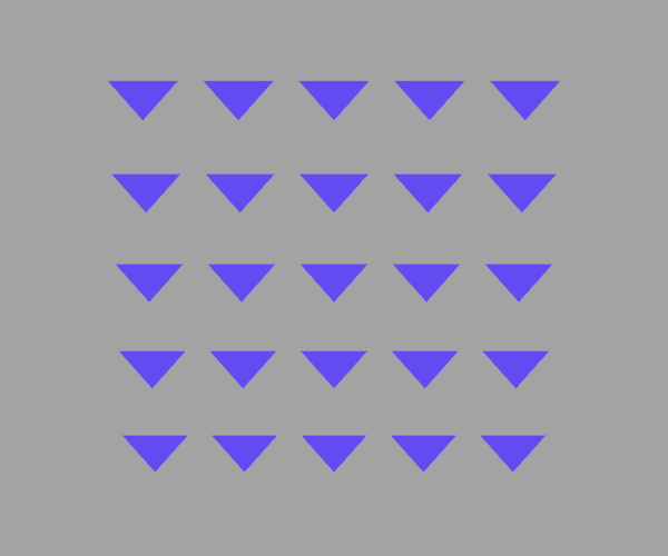
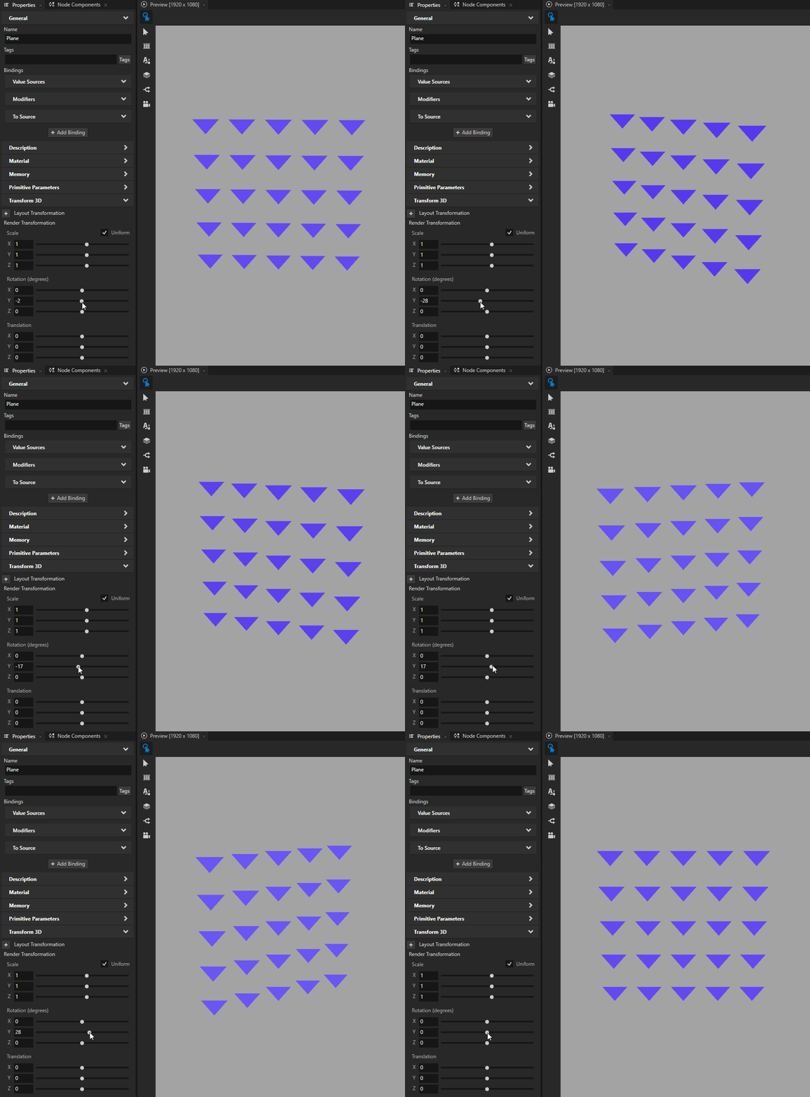
In this procedure, you use a geometry shader to draw a triangle at each vertex of a primitive mesh.
To use a geometry shader:
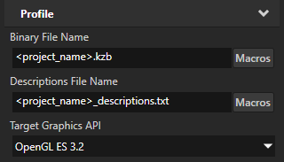
In the Kanzi Studio main menu, select Project > Properties and set the Target Graphics API to OpenGL ES 3.2.
Add a geometry shader to a material type.
For example, in the Library > Materials and Textures > Material Types, press Alt and right-click the VertexPhong material type and select Geometry Shader.
Kanzi Studio creates in the material type a Geometry Shader between the Vertex Shader and the Fragment Shader.
The source file of the Geometry Shader has the extension
.geom.glsl.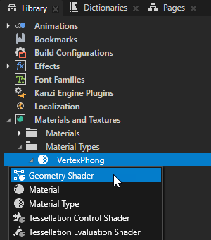
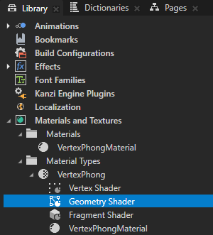
In the Library, double-click the Geometry Shader to open it in the Shader Source Editor and edit the shader code to meet you needs.
For example, to draw a triangle at each vertex of a mesh, replace the content of the geometry shader file with:
#version 320 es
// Turn triangles into three triangles by vertices.
layout(triangles) in;
layout(triangle_strip, max_vertices = 9) out;
precision highp float;

in lowp vec3 vAmbDif[];
out lowp vec3 fragColor;

void main() {
    for(int i = 0; i < 3; ++i)
    {
        fragColor = vAmbDif[i];
        gl_Position = gl_in[i].gl_Position + vec4(0, -0.5, 0, 0);
        EmitVertex();
        gl_Position = gl_in[i].gl_Position + vec4(0.5, 0.5, 0, 0);
        EmitVertex();
        gl_Position = gl_in[i].gl_Position + vec4(-0.5, 0.5, 0, 0);
        EmitVertex();
        EndPrimitive();
    }
}
Click Save.
In the material type to which you added the geometry shader, double-click the Fragment Shader to open it in the Shader Source Editor. Edit the shader code to use the output of the geometry shader.
For example, replace the content of the fragment shader file with:
#version 320 es

precision lowp float;

in vec3 fragColor;
out vec4 outColor;

void main()
{
    outColor = vec4(fragColor, 1);
}
Click Save.
Create a 3D node that renders a mesh. Set that node to use a material that uses the material type to which you added a geometry shader.
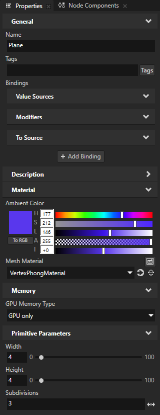
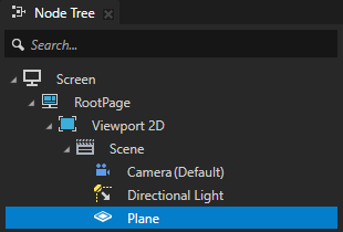
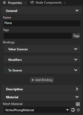
For example, in the Node Tree, create a Plane node. In the Properties, set the Mesh Material property to VertexPhongMaterial.
In the Properties, adjust the appearance of the content.
For example, add and set:
Material > Ambient Color to set the color of the triangles.
Subdivisions property to increase the number of triangles.
The Subdivisions property sets the tessellation level of a primitive mesh. A Plane node by default consists of one tile with four vertices. For example, when you set the Subdivisions property to 3, the number of vertices in the plane increases to 25. See Setting the tessellation level of a primitive mesh.
