Step 1 - Create the speed needle
In this step of the tutorial you add the speed needle to the gauges, adjust its position, and make it react to the changes in the value of a property you create.
Assets for the tutorial
The starting point of this tutorial is the <KanziWorkspace>/Tutorials/Gauges/Assets/Gauges.kzproj Kanzi Studio project.
You can find the completed tutorial in the <KanziWorkspace>/Tutorials/Gauges/Completed directory.
Open the project and add the speed needle
In this section you open the project, adjust the Preview, and add the speed needle to the gauges.
To open the project and add the speed needle:
In Kanzi Studio open the project stored in
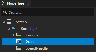
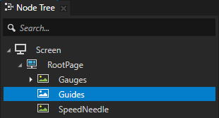
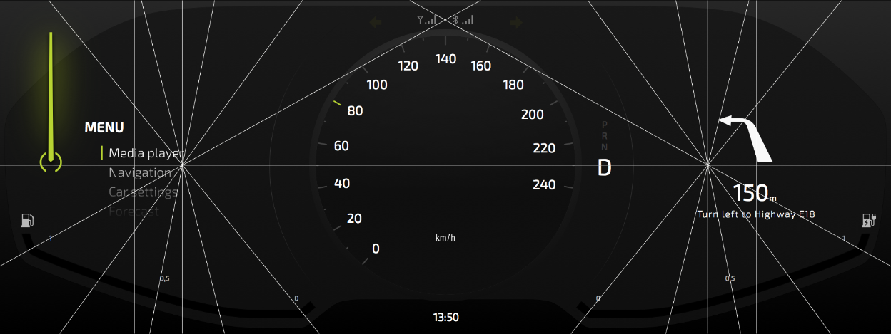
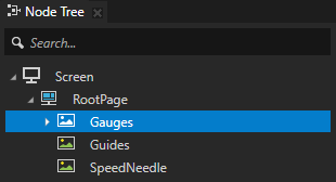
<KanziWorkspace>/Tutorials/Gauges/Assets.The project contains the Gauges Image node that is used as the background for all gauges in this tutorial and the Guides Image node you can use to precisely set the pivot points of the needles in the gauge.
Tip
If you cannot see all three gauges in the Preview, you can adjust the Preview zoom level in the upper right corner of the Preview.

Tip
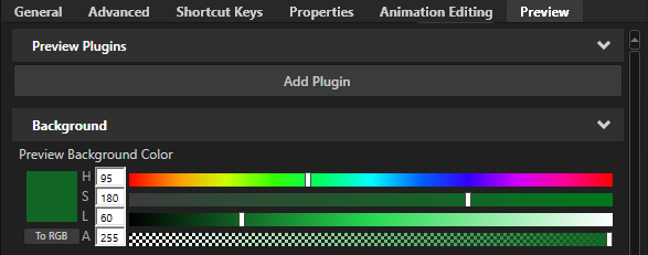
The background of the Preview is by default black. To make your content stand out from the background when the Preview is in the Interact mode
 , select Edit > User Preferences and in the Preview tab set the Preview Background Color property to the desired color.
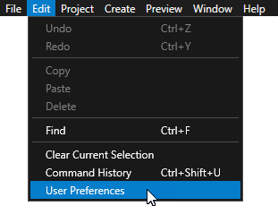
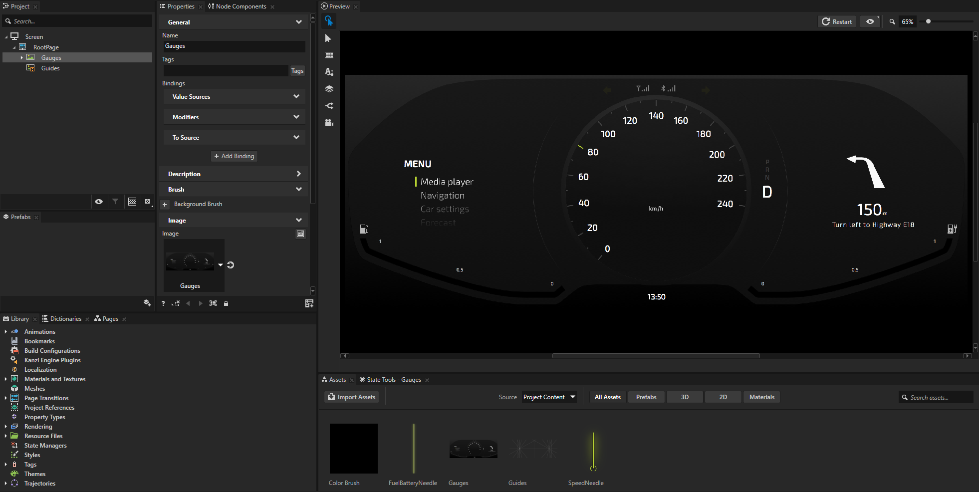
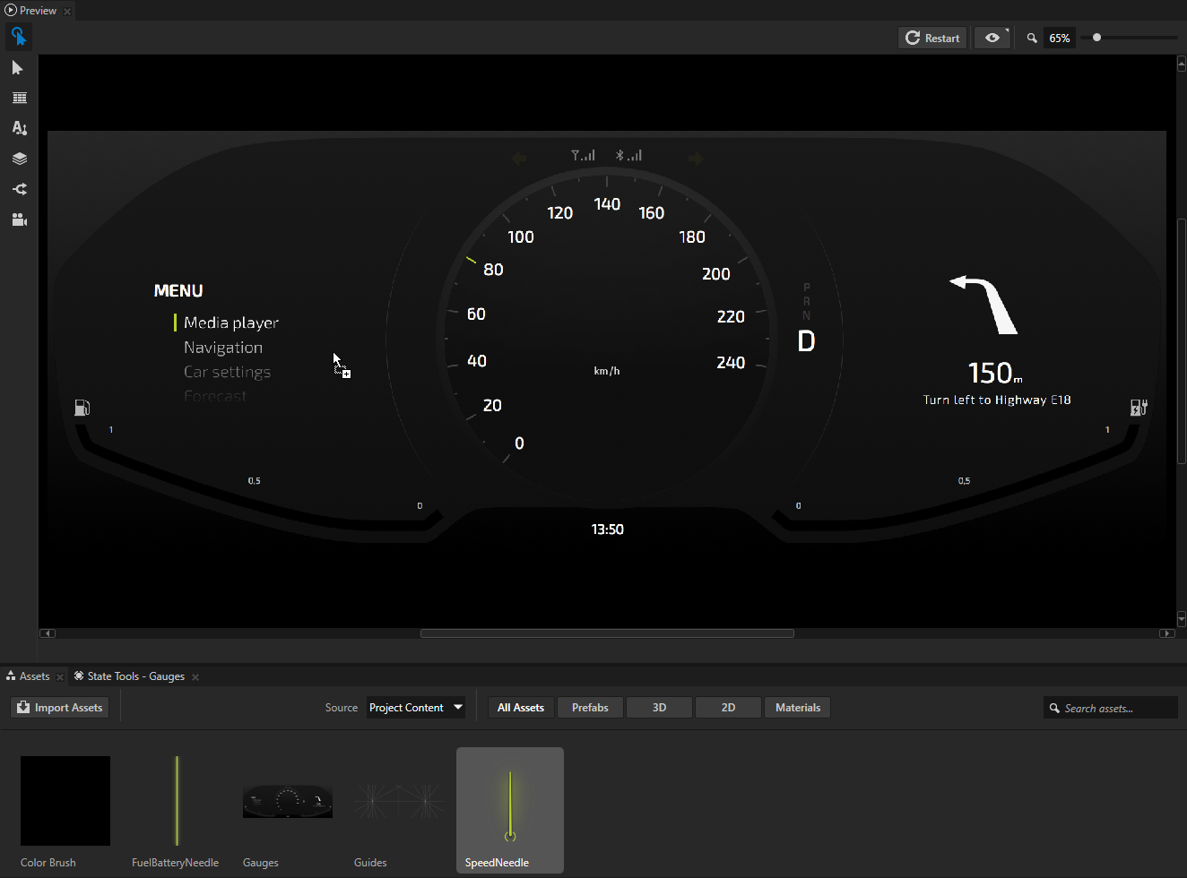
From the Assets at the bottom of the Kanzi Studio UI, drag the SpeedNeedle image and drop it on the Gauges in the Preview.
When you drag an image from the Assets to the Preview, Kanzi Studio creates a new Image node that shows the image you dragged and places it into the top left corner of the screen. In the next section you position the SpeedNeedle node to its correct position.
Adjust the position of the SpeedNeedle
In Kanzi Studio you can adjust the position of a node in the Preview using the Preview tools, or by selecting the node in the Node Tree and adjusting the value of the node properties in the Properties. In this section you use the combination of both approaches.
In this section you place the SpeedNeedle in the center of the speed gauge and adjust its origin so that it rotates correctly around the center of the gauge.
Tip
To ensure precise position of nodes, create an image that outlines the exact position of all key elements in your interface. Import the guide image to your project and use it as a guide when positioning the nodes. The project in this tutorial includes just such image.
To adjust the position of the SpeedNeedle:
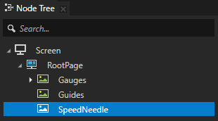
In the Node Tree select the Guides node and press Ctrl H to reveal the guides you can use to set the precise position of the needles in the gauge.
In the Preview use the Node tool
 to select the SpeedNeedle.
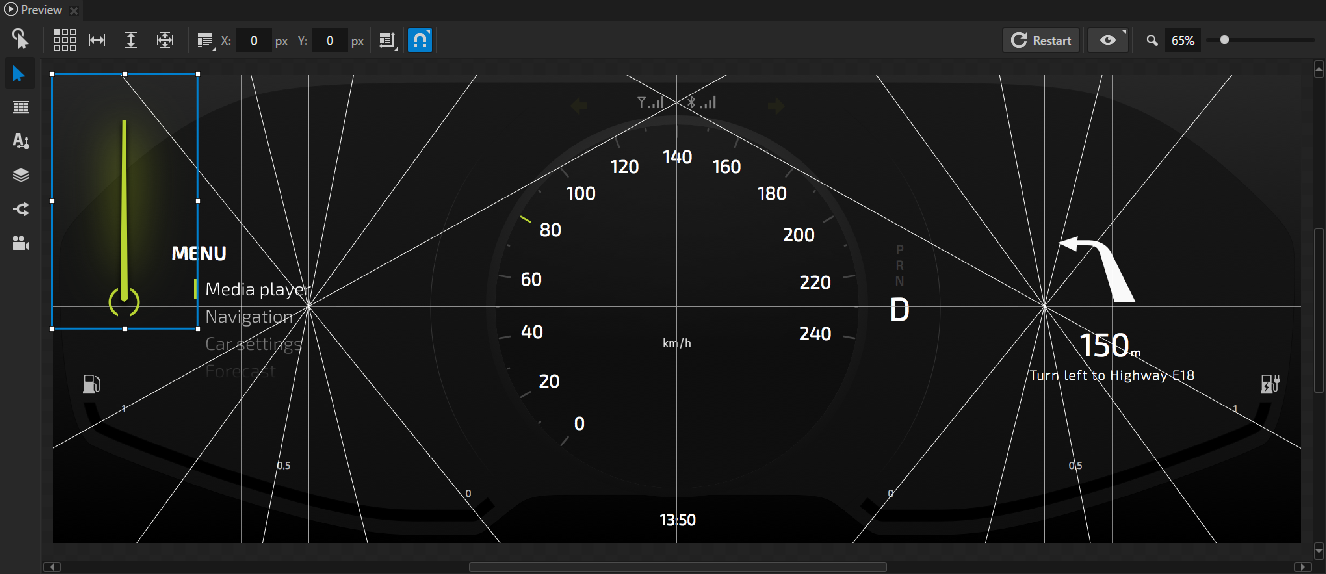
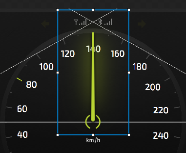
In the Node tool click the top center square
 to align the SpeedNeedle node to the top and center of its parent node, the RootPage node.
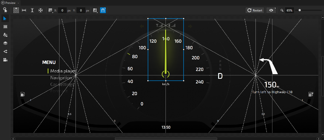
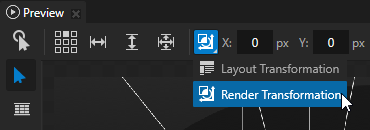
In the Node tool click
 and select Render Transformation for the target transformation.
You can apply transformations in these ways:
Layout transformation transforms the item before it applies the layout pass.
Render transformation transforms the item after it applies the layout pass, but before it renders the item.
Always use the Render Transformation, unless you know that you have to recalculate the layout.
In the Preview select the Node tool
and click  to disable snapping to nodes and guides.
When you disable snapping, you can use the Node tool to move a node in the Preview so that it does not snap to nodes or guides.
Use the Node tool to place the bottom of the needle exactly on top of the crosshair in the Guides.
Tip
Hold down the Shift key when you drag a node with the Node tool to move the node in a true horizontal or vertical line.
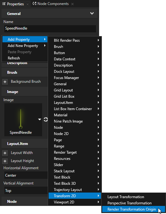
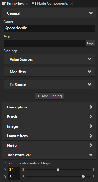
In the Node Tree select the SpeedNeedle node, in the Properties right-click, select Add Property > Transform 2D > Render Transformation Origin, and set:
X attribute to 0,5
Y attribute to 0,9
In Kanzi by default the origin of all 2D nodes is in the upper left corner of the node. Because you want to rotate the needle around the bottom center of the needle, you have to use the Render Transformation Origin to place the pivot there.
Control the SpeedNeedle with a custom property
Properties provide the means to specify and examine the state, appearance, and behavior of nodes. For example, a property can define a color, indicate whether a button is pressed, or specify the alignment of an item.
In this section you create and use a custom property to control the position of the SpeedNeedle in the gauge.
In this section you create a custom property type and use it to control the rotation of the SpeedNeedle node.
To control the SpeedNeedle node with a custom property:
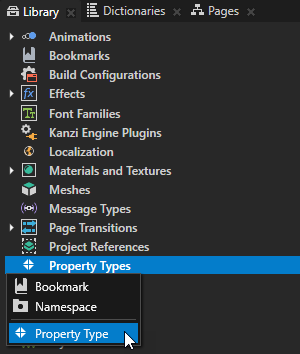
In the Library press Alt and right-click Property Types and select Property Type.
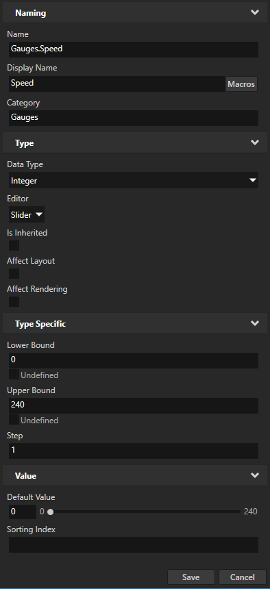
In the Property Type Editor set:
Name to Gauges.Speed
Display Name to Speed
Category to Gauges
Data Type to Integer
Lower Bound to 0
Upper Bound to 240
Click Save to create a property type with the properties you defined.
You use this custom property type to control the position of the SpeedNeedle node in the Gauges node.
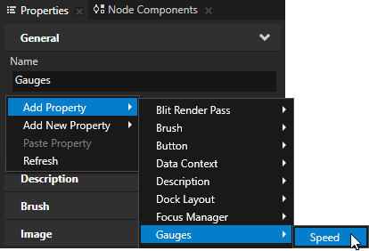
In the Node Tree select the Gauges node, in the Properties right-click, and select Add Property > Gauges > Speed.
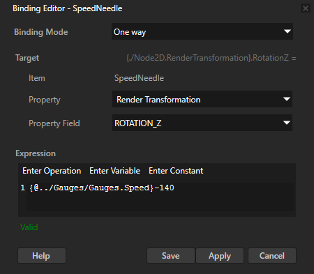
In the Node Tree select the SpeedNeedle node, in the Properties click + Add Binding, and in the Binding Editor set:
Property to Render Transformation
Property Field to Rotation Z
Expression to
{@../Gauges/Gauges.Speed} - 140You have to subtract 140 from the value of the property to correctly position the needle at value 0 on the gauge, when the value of the Speed property is 0.
Click Save.
With this modifier binding you rotate the SpeedNeedle around its z axis with the Speed property in the Gauges node you added in the previous step.
Tip
When you write expressions for bindings in the Binding Editor, the fastest and most accurate way to add nodes and their properties to an expression is to drag them from the Properties to the Expression editor in the Binding Editor.
For example, to add the Speed property in the Gauges node, in the Node Tree select the Gauges node and from the Properties drag the Speed property to the Expression field in the Binding Editor.
You can now rotate the needle by adjusting the value of the Speed property in the Gauges node.
Show the current speed as a numerical value
In this section you create a node that shows the current speed as a numerical value.
To show the current speed as a numerical value:
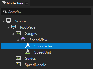
In the Node Tree press Alt and right-click the Gauges > SpeedView node, select Text Block 2D, and name the node SpeedValue.
SpeedView is a Stack Layout 2D node. The Stack Layout node places its child nodes in a stack on the axis set by its Direction property. SpeedView contains the Text Block 2D node SpeedUnit that shows the speed unit.
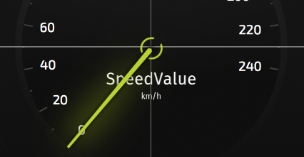
In this section you use the SpeedValue node to show the current value of the SpeedNeedle.
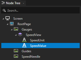
In the Node Tree drag the SpeedValue node above the SpeedUnit node to show the speed value above the speed unit in the gauge.
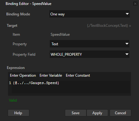
In the Node Tree select the SpeedValue node and in the Properties:
Click + Add Binding, and in the Binding Editor set:
Property to Text
Expression to
{@../../Gauges.Speed}
Click Save.
With this binding you show the current value of the Gauges.Speed property in the SpeedValue node.
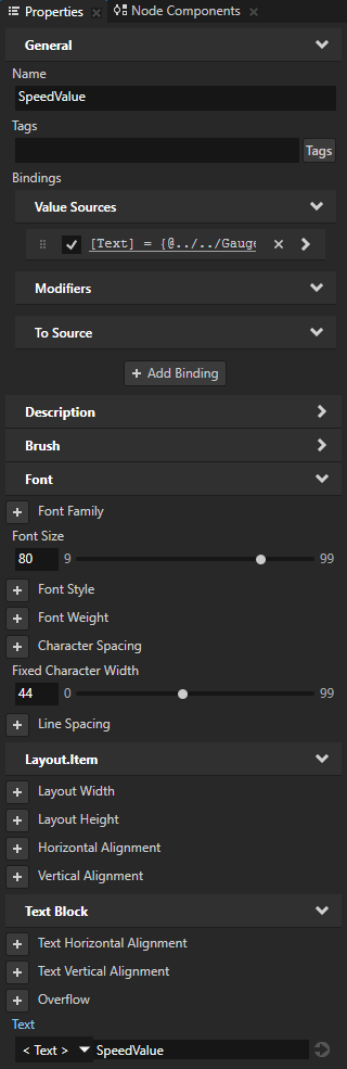
Add and set:
Font Size to 80
Fixed Character Width to 44
Use the Fixed Character Width property to turn any font into a monospaced font.
When you change the value of the Speed property in the Gauges node, you rotate the needle and show the value of the property in the SpeedValue node.